MIL-PRF-1/1383D
TABLE I. Testing and inspection - Continued.
12/
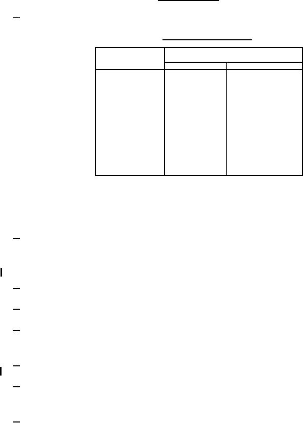
Initial compliance with the statistical life test shown in table IB shall be required. (X0 = 1,000 hours, X1 = 500 hours, a = 0.10,
β = 0.10.)
TABLE IB. Acceptance and rejection criteria.
Number of
Total number of hours
failures
of burning
(r)
Reject
Accept
0
---
2,197
1
---
2,890
2
---
3,583
3
---
4,276
4
575
4,969
1,268
5,662
5
1,961
6,355
6
2,564
7,048
7
3,347
7,741
8
4,040
8,434
9
4,733
9,127
10
5,426
9,820
11
6,119
10,513
12
X0 = Acceptable length of line in hours.
X1 = Unacceptable length of line in hours.
a = Maximum risk of rejecting tubes if the length of life is X0 or better.
β = Maximum risk of accepting tubes if the length of life is X1 or worse.
13/
It shall be essential (a) that high-quality water be used to fill the system initially, (b) that provision be made for continuous
regeneration (purification) of the system water, and (c), that steps be taken to eliminate insofar as possible the sources of
contamination. These requirements are necessary to prevent scale formation, corrosion, and excessive electrolysis. Any one
of these conditions can greatly reduce tube life. Corrosion and electrolysis contribute to water contamination. Furthermore,
they can destroy the tube elements, ducts, and fittings. If the specific resistivity of the water falls below 1.5 MegΩ-cm at 25°C,
it can be assumed the contaminants are excessive.
14/
The waterflow to the anode cooling connection shall be 14 gpm. The waterflow to the filament sections, dc cathode, grid 1
and grid 2 cooling connections shall be 1.2 gpm each.
15/
Grid 1 voltage (Ec1) is adjusted for class B operation. Class B operation is defined as that value of negative Ec1 which is
between one-fifth and one-eighth of the ec2 voltage.
16/
Circuit adjustments are permissible. The rectified rf output pulse length (tp) shall be 200 to 220 microseconds with a repetition
rate of 220 to 250 pps and duty factor 0.05 minimum. Peak output power is calculated by dividing the average output power
by the duty factor. Duty factor is defined as the product of pulse duration and the repetition rate. The average output power
is measured by a calorimetric method using a waterload.
17/
With conditions as specified, record grid 1 current (I1) after specified time. Then remove all voltages except filament voltage
and grid 1 voltage, and record grid 1 leakage current (I2). Calculate Ic from the formula: Ic = I1 I2.
18/
The frequency of the sweep generator shall be adjusted to obtain resonance curve on oscilloscope. (Be sure tube is making
good contact with cavity.) The marker oscillator frequency shall be varied until marker pip is located on peak of resonance
curve. The resonance frequency as read on frequency meter shall be within limits specified. The output cavity and input
cavity shall be as shown on figures 2 and 3. See figure 4 for typical block diagram of test circuit.
19/
Peak power output (2) test is an alternate to peak power output (1) and may be performed in place of peak power output (1) or
vice versa.
6
For Parts Inquires call Parts Hangar, Inc (727) 493-0744
© Copyright 2015 Integrated Publishing, Inc.
A Service Disabled Veteran Owned Small Business