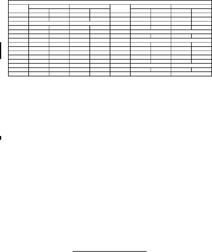
MIL-PRF-1/1383D
Dimensions
Ltr
Inches
Millimeters
Ltr
Inches
Millimeters
Min
Max
Min
Max
Min
Max
Min
Max
B
5.315
5.335
135.00
135.51
S
.244
.254
6.20
6.45
C
2.657
2.667
67.49
67.74
T
.105
.111
2.67
2.82
D
.12 R (TYP)
3.05 R (TYP)
U
.865
.885
21.97
22.48
E
3.987
3.993
101.27
101.42
V
1.740
1.760
44.20
44.70
F
4.947
4.953
125.65
125.81
W
.12 R
3.05 R
G
4.505
4.511
114.43
114.58
X
.574
.576
14.58
14.63
H
4.450
4.452
113.03
113.08
Y
.12 R
3.05 R
J
4.273
4.275
108.53
108.59
Z
4.947
4.953
125.65
125.81
K
4.169
4.175
105.89
106.05
AA
.365
.385
9.27
9.78
L
3.802
3.808
96.57
96.72
AB
.351
.357
8.92
9.07
M
3.765
3.775
95.63
95.89
AC
.990
1.010
25.15
25.65
N
.252
.258
6.40
6.55
AD
.702
.712
17.83
18.08
P
.012
.018
0.30
0.46
AE
.354 REF
8.99 REF
Q
.120
.130
3.05
3.30
AF
.247
.253
6.27
6.43
R
.153
.159
3.89
4.04
AG
.500 REF
12.70 REF
NOTES:
1. 2 holes, drill .219 inch (5.56 mm) diameter (thru) C' bore .375 (9.53 mm) diameter by .062 inch (1.57 mm) deep.
2. Grid No. 1 contact groove to be filled with the following spring: .020 inch (0.51 mm) diameter wire wound to give a .250
inch (6.35 mm) O.D. at 35 TPI, 14.25 inches (361.95 mm) in length (approximate).
3. Moat shall be filled with a braid to insure continuous braid contact and yet permit firm seating of the cavity on the RF
cathode terminal contact surface.
4. Location of A-N connector - UG-290/U (two connectors 180 degrees apart).
5. 2 holes. Drill and tap for #3-48 screws.
6. 3 holes. Drill and tap for #3-48 screws by .188 inch (4.78 mm) deep.
7. Cylindrical holes G to M have axes coincident within .001 inch (0.03 mm).
FIGURE 3. Input cavity required for resonant frequency test - Continued.
13
For Parts Inquires call Parts Hangar, Inc (727) 493-0744
© Copyright 2015 Integrated Publishing, Inc.
A Service Disabled Veteran Owned Small Business