MIL-PRF-1/1383D
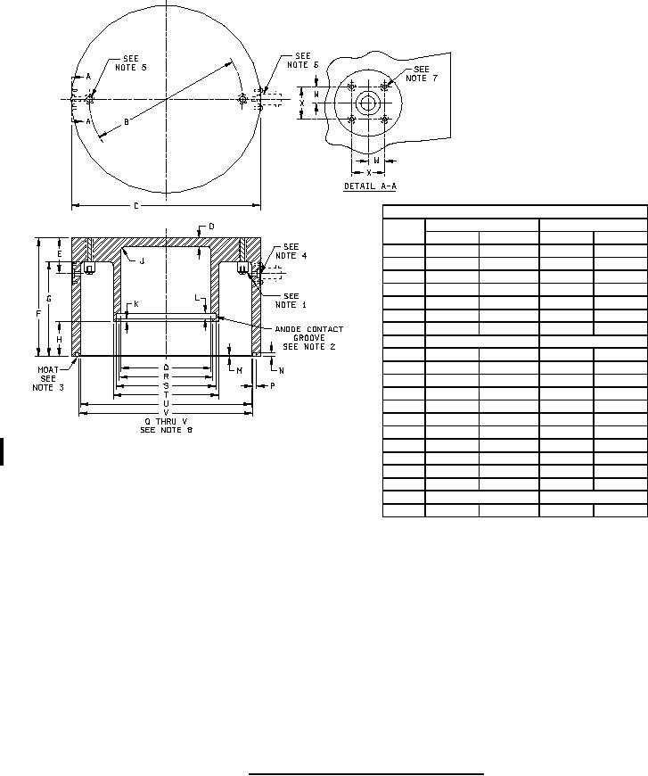
Dimensions
Ltr
Inches
Millimeters
Min
Max
Min
Max
B
6.397
6.403
162.48
162.64
C
7.885
7.905
200.28
200.79
D
.365
.385
9.27
9.78
E
1.485
1.515
37.72
38.48
F
4.985
5.015
126.62
127.38
G
3.995
3.997
101.47
101.52
H
1.466
1.468
37.24
37.29
J
.12 R (TYP)
3.05 R (TYP)
K
.098
.104
2.49
2.64
L
.253
.259
6.43
6.58
M
.009
.015
0.23
0.38
N
.107
.113
2.72
2.87
P
.153
.159
3.89
4.04
Q
3.770
3.780
95.76
96.01
R
3.805
3.811
96.65
96.80
S
4.169
4.175
105.89
106.05
T
4.401
4.403
111.79
111.84
U
7.145
7.147
181.48
181.53
V
7.243
7.249
183.97
184.12
W
.250 REF
6.35 REF
X
.490
.510
12.45
12.95
NOTES:
1. 2 studs. 1.5 inch (38.1 mm) long threaded .25 inch (6.35 mm)-20 NC by 1.0 inch (25.4 mm) with .375 inch (9.53 mm)
diameter head. Head of stud shall be drilled and tapped .25 inch (6.35 mm) deep for #6-32 RH machine screw. Use
standard .156 inch (3.96 mm) flat washer under screw.
2. Anode contact groove shall be filled with the following spring: .020 inch (.51 mm) diameter wire wound to give a .250
inch (6.35 mm) O. D. at 35 TPI, 14.25 inches (361.95 mm) in length (approximate).
3. Moat shall be filled with a braid to insure continuous braid contact and yet permit firm seating of the cavity on the rf
cathode terminal contact surface.
4. 2 holes. Drill .219 inch (5.56 mm) diameter (thru), C' bore .375 inch (9.53 mm) diameter by .125 inch (3.18 mm) deep.
Spot face 1 inch (25.4 mm) diameter by .062 inch (1.57 mm) deep.
5. 2 holes. Drill and tap for .250 inch (6.35 mm) -20 NC screws.
6. Location of A-N connector - UG-290/U (two connectors 180 degrees apart).
7. 4 holes. Drill and tap for #3-48 screws by .250 inch (6.35 mm) deep.
8. Cylindrical holes Q to V have axes coincident within .001 inch (0.03 mm).
FIGURE 2. Output cavity required for resonant frequency test.
11
For Parts Inquires call Parts Hangar, Inc (727) 493-0744
© Copyright 2015 Integrated Publishing, Inc.
A Service Disabled Veteran Owned Small Business