MIL-PRF-1/1701C
TABLE I. Testing and inspections - Continued.
15/
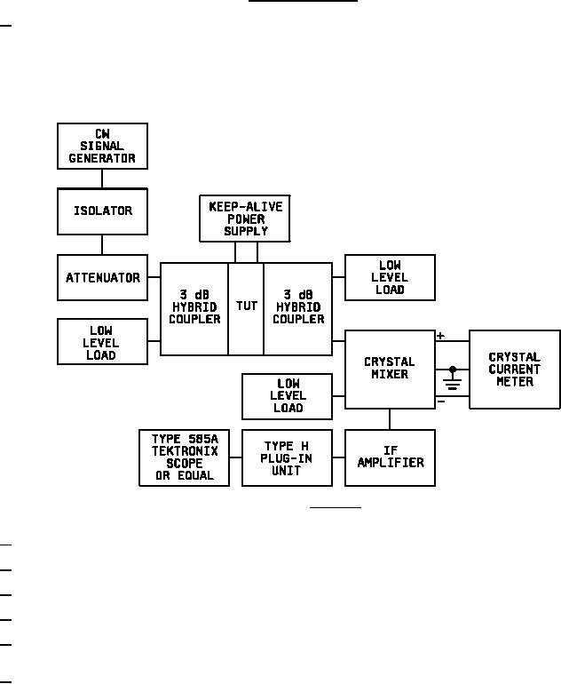
The ignitor current noise test is performed in a circuit setup as shown on figure 4. With the rated voltage applied to the shutter and
the ignitor, adjust the CW signal from the signal generator to 16.2 GHz. By means of the attenuator, set the crystal current as
shown on the meter to 0.5 mA to 0.6 mA. Set the scope internal sweep for 50 µs/cm and the vertical (type H plug in) for 5 mv/cm,
or higher. Vary the signal frequency slowly from 15.8 to 17.0 GHz. If the tube under test is noisy, high amplitude, sharp spikes
about 10 µs apart will appear on the scope above the "grass" level. If these spikes can be made to disappear by turning the keep-
alive voltage off, the tube is noisy and shall be rejected.
FIGURE 4. Test circuit.
16/
Swept frequency signal may be used for this test.
17/
The leakage power (flat) and leakage energy (spike) shall be measured at the load arm of the duplexer.
18/
The leakage power (flat) and leakage energy (spike) shall be measured at the receiver arm of the duplexer.
19/
Shutter current shall be measured at rated voltage and 60 seconds after application of this voltage.
20/
Each time the shutters open, a low-level signal is transmitted through the tube and is registered on a counting circuit. At the end of
this test, the number of pulses received should equal the number of pulses applied to the shutters.
21/
The crystal noise figure degradation from the initial value shall not exceed the specified limit. One crystal failure will be allowed
during the life test. If a crystal failure occurs, a new crystal shall be inserted in the mount and the life test shall continue for a
minimum of 100 hours.
8