MIL-PRF-1/1701C
TABLE I. Testing and inspections - Continued.
5/
The phase length of the tube shall be measured relative to an equivalent length of RG-91/U waveguide. The phase slope deviation
shall not exceed ±1.5 degrees (max) at any operating frequency.
6/
When using a phase shifter (rotary vane type such as a Hewlett-Packard No. P885A, or equivalent) record the phase shifter dial
reading using only the top scale and vernier, when the circuit has been balanced.
7/
The static phase unbalance between the two channels of the tube shall be less than the specified value and shall not deviate from
the equivalent line length with frequency by more than 1.5 degrees.
8/
The recovery time shall be measured at the point where the signal level has recovered to within 0.5 dB of the full-signal level.
9/
With the static phase error balanced, the dynamic phase unbalanced between the two channels shall be less than the specified
value of 1.0 microseconds. Recovery time shall be compatible with dynamic phase.
10/
The shutter shall be held open during vibration by the specified minimum voltage. Vibrate in a plane parallel to the axes of the
shutters. The insertion loss test set up shall be used with the unit under test mounted on the vibrator such that a standard
waveguide section of similar geometry may be substituted for the shutter tube. The modulation (ĆLi) due to vibration shall not be
greater with the shutter tube in the line than with the waveguide section.
11/
Shutter phase modulation.
a. Introduction. The measurement of rf phase modulation introduced during vibration of the shutter mechanisms in crystal
protector tubes can be performed by either of the two indirect techniques to be described. Direct measurement of this
parameter is not practical because the phase modulation introduced by the waveguide test equipment will generally be far
greater than the permissible shutter modulation.
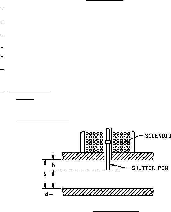
b. Description of shutter mechanism.
FIGURE 1. Sketch of shutter mechanism.
The shutter pin is attached to a magnetic armature which is located in the magnetic field set up by a solenoid. In the
absence of solenoid voltage, the shutter pin is forced against the opposing wall by the force of a shutter closing spring.
The rf gap "g" is shorted in this condition and reflects incident signals. With the application of solenoid voltage, the
shutter pin is withdrawn from the rf gap against the force of the spring and comes to rest at a height "h" above the
opposing wall. Under this condition, the shutter mechanism introduces no appreciable loss to rf signals passing
through the crystal protector tube.
5