MIL-PRF-1/1701C
TABLE I. Testing and inspections - Continued.
e.
Optical measurement technique. The wall surrounding the shutter pin is cut back or removed entirely in order to expose the
shutter pin for optical observation. The shutter mechanism is then mounted on a suitable vibration table and the shutter pin is
observed through a rigidly mounted telescope. The shutter is illuminated by a strobe light which is synchronized to the motion
of the vibration table. The telescope is aimed so that a reference marker (e.g., crosshairs) is pointed at the critical distance
"d" from the wall opposing the shutter pin. The shutter pin is then withdrawn from the opposing wall by application of the
reduced shutter voltage and the assembly is vibrated over the applicable range. Any travel of the shutter pin from its fully
withdrawn position (distance "d" from the opposing wall) is observed through the telescope. The extent of this travel shall not
reach beyond the critical spacing "d".
f.
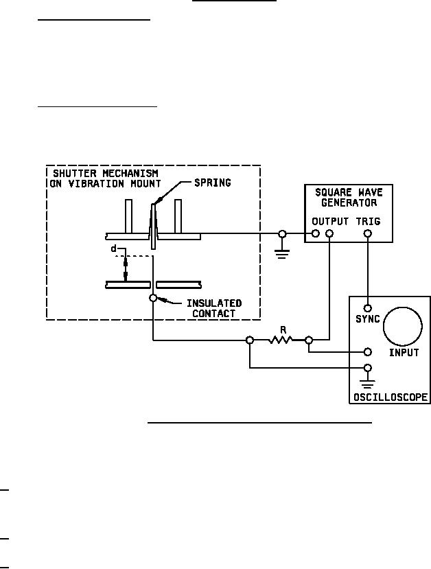
Electrical measurement technique. For this technique, the opposing wall is drilled out similarly to the wall containing the
shutter pin. An insulated electrical contact is then passed through this wall and adjusted until its tip is at the distance "d"
above the end of the shutter opposing wall. The wall surrounding the shutter pin is cut back or removed as for the optical
technique. The electrical connections are then made as shown on figure 3. The shutter pin is maintained at case potential
through the shutter closing spring.
FIGURE 3. Test setup for electrical measurement shutter phase modulation.
g.
The shutter is now vibrated through the specified range. Contact with the insulated electrical contact is made whenever the
shutter pin travel comes within the distance "d" of the opposing wall. Current will then flow through the resistor "R", and the
monitoring oscilloscope will display the waveform of the square-wave generator under vibration.
12/
The current required to hold the shutter open shall be within the specified limit when the tube is subjected to the following shock
test: The tubes shall sustain 18-impact shocks (three in each direction of the three mutually perpendicular axes) each shock
having a half-sine pulse with perpendicular value 50 g's duration of 11 ± 1 ms. The shutter shall be capable of meeting the
requirement over the temperature range extending from -55°C to +125°C.
13/
Unless otherwise specified, the acceptance level for all tests listed under conformance inspection, part 1, shall be 1.0, inspection
level II.
14/
Test each section separately.
7