MIL-PRF-1/1701C
TABLE I. Testing and inspections - Continued.
c.
Phase calibration.
(1)
A shutter mechanism consisting of the shutter pin and the two opposing walls is assembled into a flanged section of
waveguide. A calibrated micrometer drive is attached to the shutter pin and permits manual drive of the pin from the
shorted condition (i.e., shutter pin resting against the opposing wall) to the "open" condition (i.e., shutter pin at a
distance "d" from the opposing wall).
(2)
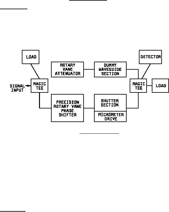
The waveguide section containing the micrometer driven shutter assembly is inserted into an rf phase bridge as shown
on figure 2.
FIGURE 2. Shutter phase calibration.
(3)
Using the micrometer drive, the shutter pin is driven against the opposing wall and the phase bridge is balanced with
the phase shifter. A balanced condition, as indicated by a null at the detector output, will require insertion of
attenuation in the attenuator leg to compensate for the isolation of the shutter. An exact balance is not required at this
point. The micrometer reading for this shorted condition of the shutter is recorded.
(4)
The shutter pin is then retracted from the shorted condition in small increments and the phase bridge rebalanced at
each micrometer setting. Both the attenuator and the phase shifter shall be reset at each balancing in order to obtain
the maximum depth of null at the detector. It will be noted that the amount of phase shifter change required per
increment of micrometer movement will diminish as the shutter pin moves out of the gap "g".
(5)
Further retraction of the shutter pin outside the gap region will lead to a critical separation "d", beyond which the motion
of the shutter pin no longer has any effect on the phase characteristic of the assembly. This condition will be
evidenced by the fact that the bridge will remain in balance (null at the detector) without requiring further adjustment of
the phase shifter. The micrometer reading at the critical separation "d" is then subtracted from the initial reading at the
shorted condition to establish the value of "h".
d.
Vibration testing. Vibration testing shall be carried out over the frequency range extending from 10 to 500 Hz to
10 Hz at a
0.06-inch double amplitude displacement (to a maximum of 10 G) in accordance with MIL-STD-202, method 204, test
condition A. In order to avoid phase modulation, the shutter pin separation from the opposing wall shall always be greater
than the critical spacing "d" for all conditions of vibration. Either optical or electrical means may be used to demonstrate that
the shutter design has satisfied this requirement. The voltage applied to the shutter solenoid shall be the minimum allowable
under the applicable specification (21 V dc). The shutter shall be vibration tested at the minimum shutter holding power level
determined under quiescent conditions at Es = 21 V dc and TA = +125°C.
6