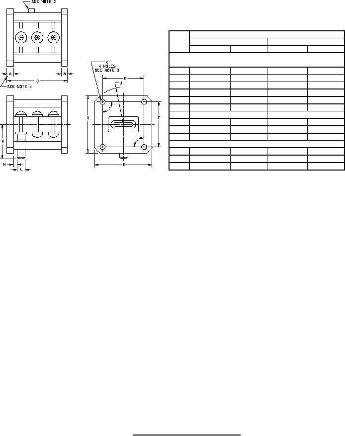
MIL-PRF-1/1000B
Dimensions
Ltr
Inches
Millimeters
Min
Max
Min
Max
Conformance inspection, part 1
(see note 5)
A
.190
.220
4.83
5.59
B
.190
.220
4.83
5.59
C
1.973
1.993
50.11
50.62
D
1.844
1.906
46.84
48.41
E
1.844
1.906
46.84
48.41
J
1.125 R
1.188 R
28.58 R
30.18 R
K
.169 DIA (see note 3)
4.29 DIA (see note 3)
L
.245 DIA
.255 DIA
6.22 DIA
6.48 DIA
M
.156
---
3.96
---
N
---
1.281
---
32.54
Conformance inspection, part 2
F
1.468
1.480
37.29
37.59
G
1.356
1.368
34.44
34.75
89.5°
90.5°
89.5°
90.5°
P
NOTES:
1. Silver plate 100 MSI, or equivalent.
2.
Exhaust tube shall not extend beyond flange more than .25 inch (6.35 mm).
3.
The rectangle formed by the centers of the four .169 inch (4.29 mm) diameter holes shall be centered on the flange face
within .031 inch (.794 mm).
The planes of the two waveguide-flange surfaces shall be parallel within ± .002, maximum.
4.
5.
Unless otherwise specified, the acceptance level for all tests listed under conformance inspection, part 1, shall be 1.0 in
accordance with MIL-PRF-1, Table III accept on zero (c = 0) sampling plan.
FIGURE 1. Outline drawing of electron tube type 6164.
4
For Parts Inquires call Parts Hangar, Inc (727) 493-0744
© Copyright 2015 Integrated Publishing, Inc.
A Service Disabled Veteran Owned Small Business