MIL-PRF-1/1705C
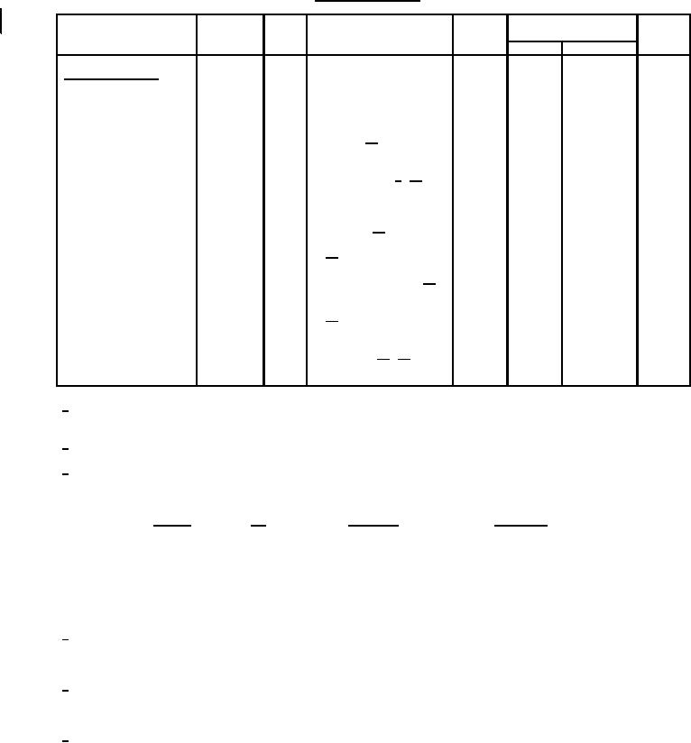
TABLE I. Testing and inspection - Continued.
MIL-STD-
Limits
1311
Inspection
Method
Test
Conditions
Symbol
Min
Max
Unit
Periodic check tests -
Continued
MP
---
0.2
%
Stability (2)
4315
2
Ef = 6 ± .0.3 V;
F = F1, F3, and F5;
Ib = 30 A 11/
T
---
Air cooling
1143
2
TA = +80°C
°C
TA = 25°C;
2/ 16/
Pi-Po = 500 W
Torque
---
15.0
In-oz.
---
---
No voltages
High-low temperature
tuning torque
temperature = -55°C
to +125°C 17/
Mechanical tuning fatigue
4223
---
18/
---
25,000
---
cycles
Thermal frequency shift
4030
2
---
15
MHz
F = F5; t = 15 ± 5 sec 19/
ĆF
---
---
18
MHz
t = 20 min
ĆF
Temperature cycling
20/
---
---
---
---
1027
---
(nonoperating)
1031
---
No voltages 10/ 21/
Variable-frequency
---
---
---
---
vibration (nonoperating)
1/ The tuner drive shall be capable of supplying a minimum of 15 inch-ounces of torque to the magnetron tuning shaft and shall never
supply more than 8.0 inch-pounds of torque (including inertial effects) under stable conditions.
2/ The temperature is to be measured at the point indicated on figure 1.
3/ Prior to the application of high voltage, the cathode shall be heated to the required initial operating temperature. This shall be done
by applying 9.0 volts ± 5 percent for 180 seconds minimum. On the application of anode voltage; the heater voltage shall be
reduced according to the following:
tpc (µs)
Du
Ib (mA dc)
Ef (V) ±5%
Standby
---
---
9.0
0.25 to 0.30
.0004
Test condition 1
8.0
0.45 to 0.55
.001
Test condition 4
5.0
0.9 to 1.1
.0008
Test condition 2
6.0
0.9 to 1.1
.0003
7.5
8.0
2.25 to 2.75
.001
Test condition 3
5.0
4/ The rate of rise of voltage (rrv) shall be expressed in kilovolts per microsecond (kv/µs) defined by the steepest tangent to the leading
edge of the voltage pulse above the 80 percent amplitude point. Any capacitance used in the viewing (measuring) circuit shall not
exceed 6 pF.
5/ The seal formed by clamping the magnetron mounting plate against the magnetron test fixture detail of figure 3 or equivalent shall be
hermetically tight for one minute minimum with the specified air pressure applied so as to surround the entire input bushing below
the mounting plate.
6/ The seal formed by clamping the magnetron output flange against the magnetron test fixture detail of figure 4 or equivalent shall be
hermetically tight for one minute minimum with the specified air pressure applied internally to the waveguide.
4
For Parts Inquires call Parts Hangar, Inc (727) 493-0744
© Copyright 2015 Integrated Publishing, Inc.
A Service Disabled Veteran Owned Small Business