MIL-PRF-1/160N
Pin connections
Pin no.
Element
g2
1
k
2
h
3
k
4
int con
5
k
6
h
7
k
8
g1
center post
a
radiator
g2
base ring
NOTES:
Dimensions in inches with metric
equivalents (mm) in parentheses
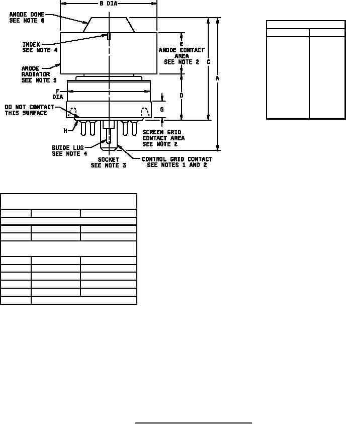
1. Pin alignment shall be checked by means of
Ltr
Minimum
Maximum
JEDEC gage GB8-3. Dimensions of control-grid
Conformance inspection, part 2
contact shall be inspected by means of gages
A
2.224 (56.49)
2.414 (61.32)
specified on Drawing 246-JAN (see note 13) and
C
1.710 (43.43)
1.860 (41.24)
shall be conformance inspection, part 2.
Conformance inspection, part 3
2. Alignment of anode, screen-grid, and control-
(periodic check) (See note 7)
grid contact surfaces shall be determined by
B
1.610 (40.89)
1.640 (41.66)
means of gage specified on Drawing 168-JAN (see
D
0.750 (19.05)
0.810 (20.57)
note 13). Conformance inspection, part 2, shall
E
0.710 (18.03)
0.790 (20.07)
apply.
F
---
1.406 (35.71)
3. Air system socket shall be as specified on
G
0.187 (4.75)
---
Drawing 246-JAN (see note 13).
H
Base: B8-236 (EIA) (See note 1)
4. Location of guide lug of control-grid contact may
be referenced by a notch or arrow on the anode
radiator in the position shown.
5. Anode clamping shall be confined to the anode radiator.
6. Dome contour shall be such that it will be contained within crosshatched area of template shown on figure 3.
Optical comparator techniques are normally used for this purpose.
7. Perform on a sample of 10 tubes from the first production lot of each year, with one failure allowed. In case
of a sample failure, the failing dimension(s) shall become part of conformance inspection, part 2 for three consecutive
successful submissions at which time the test may revert to the yearly periodic basis.
FIGURE 1. Outline drawing of electron tube type 1034.
7
For Parts Inquires call Parts Hangar, Inc (727) 493-0744
© Copyright 2015 Integrated Publishing, Inc.
A Service Disabled Veteran Owned Small Business