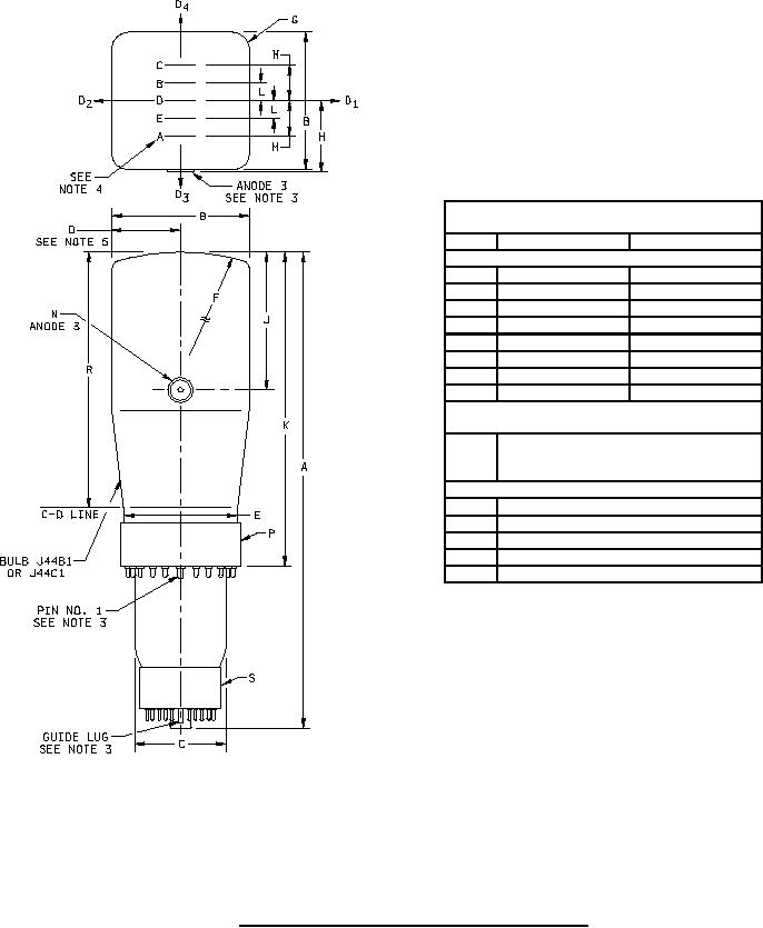
MIL-PRF-1/422J
Dimensions in inches with metric
equivalents (mm) in parentheses
Ltr
Minimum
Maximum
Conformance inspection, part 2
A
18.125 (460.38)
18.875 (479.42)
B
5.438 (138.13)
5.531 (140.49)
C
3.688 (93.68)
3.813 (96.85)
D
2.250 (57.15)
E
4.344 (110.34)
4.468 (113.49)
H
2.797 (71.04)
J
5.125 (130.18)
5.375 (136.52)
K
12.125 (307.98)
12.375 (314.32)
Conformance inspection, part 3
(See note 5)
N
Bulb contact: J1-22
Base, collar: A22-101
P
Base, B25-139 (See note 2)
S
Reference dimensions (See note 1)
F
40.00 (1016.0)
G
0.75 (19.0)
L
0.75 (19.0)
M
1.50 (38.1)
R
10.00 (254.0)
NOTES:
1.
These dimensions are for information and are not required for inspection purposes.
2.
For pin alignment use JEDEC gage GB25-1.
3.
Bulb contact J1-22, pin number 1 of base A22-101, and guide lug of base B25-139 shall each align with 3D4
trace within 10°.
4.
Beam A shall center on position A as shown within 0.312 R. This requirement shall also apply to beams B, C,
D, and E and their corresponding positions.
5.
Useful screen radius.
6.
Lancaster Glass bulb outline A-4314 or equivalent.
FIGURE 1. Outline drawing of electron tube types 7YP1, 7YP2 and 7YP7.
6
For Parts Inquires call Parts Hangar, Inc (727) 493-0744
© Copyright 2015 Integrated Publishing, Inc.
A Service Disabled Veteran Owned Small Business