MIL-PRF-1/422J
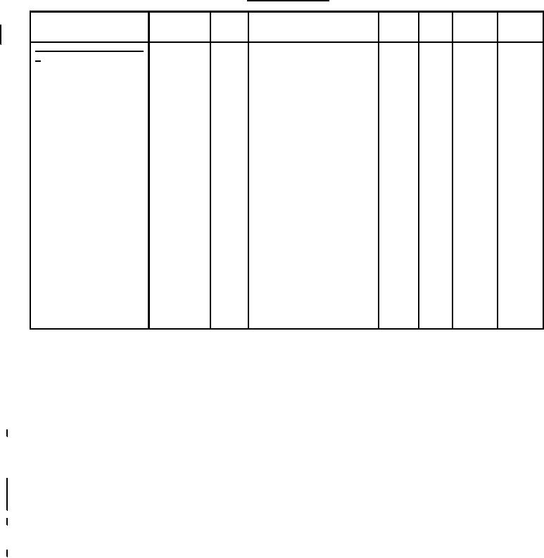
TABEL I. Testing and inspection -Continued.
Inspection
Method
Notes
Conditions
Symbol
Limits
Limits
Unit
MIL-STD-
Min
Max
1311
Conformance inspection, part
3 - Continued
6.5
---
Ck
k to all
4, 5
pF
1331
Direct-interelectrode
7.0
---
Cg1
g1 to all
pF
capacitance
2.7
---
C1D2
D1 to D2
pF
3.2
---
C3D4
D3 to D4
pF
8.1
---
CD1
D1 to all
pF
8.0
---
CD2
D2 to all
pF
7.8
---
CD3
D3 to all
pF
7.8
---
CD4
D4 to all
pF
---
---
---
5
---
5101
Neck and bulb alignment
(electrostatic types)
---
---
---
Eb2 = 3,850 V dc;
5
---
5216
Stray light emission
Eb3 = 7,700 V dc
(conventional types)
---
---
---
For qualification only
5
---
5216
Cathode illumination
2
---
---
1D2
5
%
5248
Deflection-factor
5
---
---
3D4
%
uniformity
-6
10x10
---
---
5
in./V dc
5250
Interaction factor
---
---
For qualification only
5
---
5115
---
Shock
---
---
For qualification only
5
---
1216
---
Base material insulating
quality
NOTES:
1. The deflection electrode circuit resistance should be 1 MΩ or less and approximately equal, otherwise beam shift at high
drives can be expected. Higher resistance values up to 5 MΩ may be used for low-beam current operation.
2. This tube is designed for optimum performance when operating at an Eb3/Eb2 ratio of 2.0. Operation at other ratios of
Eb3/Eb2 may result in changes in deflection uniformity and pattern distortion.
3.
All tests except direct-interelectrode capacitance, vibration and interaction factor, shall be made on each unit separately.
Each deflection plate shall be connected to A2 through a resistance of 1 MΩ ± 10%.
4. All other electrodes contained within the envelope are to be tied together.
5. This test shall be performed during the initial production and once each succeeding 12-calender months in which there is
production. A sampling plan shall be used, with sample of three tubes with an acceptance number of zero,. In the event of failure,
the test will be made as a part of conformance inspection, part 2, with an Acceptance Level of 6.5 (see note 16). The regular "12
calendar month" sampling plan shall be reinstated after three consecutive samples have been accepted.
6. The pattern size shall be adjusted to 1.5 inches (38 mm) in the limited scan direction.
7. Due to limited scan of 3D4 plates, the length of scan in the 3D4 direction shall be limited to ±1 inch from the undeflected spot
position. Line width "B" shall be measured at ± 0.75 inch (± 19.1 mm) from the undeflected spot position.
8. From the spot positions as indicated on figure 1.
4
For Parts Inquires call Parts Hangar, Inc (727) 493-0744
© Copyright 2015 Integrated Publishing, Inc.
A Service Disabled Veteran Owned Small Business