MIL-PRF-1/22J
NOTES:
1.
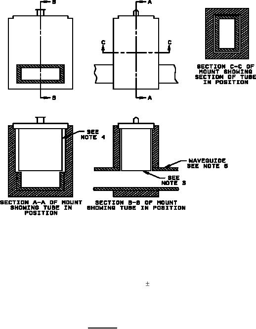
Design of holder optional.
2.
Tube shall be held firmly in position by means of spring or screw clamps.
3.
Bottom of the tube shall be flush with inside surface of waveguide within 0.004.
4.
Clearance between tube walls and inner surface of mount shall be 0.030 to 0.040.
5.
Waveguide shall be RG-52/U for the 1B35A, 1B37A, and 6162; and RG-51/U for the 5864. It is
recommended that the RG-52/U waveguide be pressurized to prevent pulse power breakdown
at 250 kw. The RG-52/U and RG-51/U waveguides shall be in accordance with MIL-W-85/1.
FIGURE 2. Test mount.
Custodians:
Preparing activity:
Army - CR
DLA - CC
Navy - EC
Air Force - 85
(Project 5960-3436)
Review activities:
Army - MU
Navy - AS, CG, MC, OS, SH
Air Force - 11, 99
5
For Parts Inquires call Parts Hangar, Inc (727) 493-0744
© Copyright 2015 Integrated Publishing, Inc.
A Service Disabled Veteran Owned Small Business