MIL-PRF-1/1733A(NAVY)
TABLE I. Testing and inspection - Continued.
b.
Liquid cooling. Liquid cooling of the filament block, dc cathode block, grid(1) block, grid(2) block, and anode, is required.
When the environmental temperature is above 0GC, the coolant may be water. The liquid flow shall start before application of
any voltages and preferably shall continue for several seconds after removal of all voltages. Interlocking of the liquid flow
through each of the cooled elements with all power supplies is recommended to prevent tube damage in case of failure of
adequate liquid flow. Liquid flow shall be as shown in table IA.
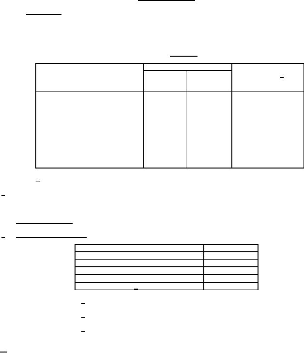
TABLE IA. Liquid flow.
Waterflow
Maximum pressure
Coolant course
Absolute
differential 1/
for typical flow
minimum
Typical
(psi)
(gpm)
(gpm)
With water:
Through filament block - - - - - - - - - -
0.5
0.8
8
Through dc cathode block- - - - - - - -
0.5
0.8
8
Through grid(1) block - - - - - - - - - - -
0.5
0.8
6
Through grid(2) block - - - - - - - - - - -
0.5
0.8
8
Through anode in direction shown
on figure 1:
For anode dissipation up to
11 kW (average) - - - - - - - - - -
8
10
10
For anode dissipation of
14 kW (average- - - - - - - - - - -
10
12
15
1/ Directly across cooled element.
8/
The water flow to the anode cooling connection shall be 8 +1, -0 gpm. The minimum water flow to the filament, filament-cathode,
grid(1) cooling connections, shall be 0.5 gpm. Water flow shall start before the application of any voltages, and shall be continued
for at least 6 seconds after removal of all voltages. The outlet water temperature shall not exceed +70GC.
Emergency conditions: Simultaneous interruption of cooling pump and tube electrode power is permissible.
9/
Environmental requirements.
External gas pressure (absolute) 1/
60 psi (max) 2/
Gage pressure at any inlet
100 psi (max)
Metal-surface temperature
100GC max
Ceramic bushing temperature
150GC max
Outlet liquid temperature (any outlet) for water
70GC max
Storage temperature 3/
-65GC max
1/ Absolute pressure is the sum of the atmospheric pressure
and gage pressure.
2/ This pressure is related to the output cavity pressurization as
required to prevent corona or external flashover.
3/ The tube coolant ducts shall be free of liquid before storage or
shipment of the tube to prevent damage from freezing.
10/
High-speed electronic protective devices shall be used to prevent energy from the anode power supply, from the grid(1) power
supply, and from the grid(2) power supply from permanently damaging the tube and its circuitry in the event of abnormal operation.
A suitable high-speed electronic protective device shall be capable of deactivating the various pulse sources supplying the tube
during the inter-pulse interval following the occurrence of a fault in any single pulse, and shall be capable of meeting the
requirements of the aluminum foil simulated fault tests. Thus, all pulses subsequent to a "fault" pulse shall not be applied until the
device is reset. (A fault is a condition in which the peak pulse currents rise 20 percent or more above the normal peak current
level.) Additional protection against damage from an anode-to-grid(2) fault shall be provided to prevent the grid(2) voltage from
rising to a value in excess of 3,000 volts during the fault pulse. Minimum reset time shall be 1 second.
5
For Parts Inquires call Parts Hangar, Inc (727) 493-0744
© Copyright 2015 Integrated Publishing, Inc.
A Service Disabled Veteran Owned Small Business