MIL-PRF-1/1733A(NAVY)
Dimensions
Ltr
Inches
Millimeters
Min
Max
Min
Max
A
.250 REF
6.35 REF
B
.490
.510
12.45
12.95
C
6.397 6.403 162.48 162.64
DIA
DIA
DIA
DIA
D
7.885 7.905 200.28 200.79
E
1.485 1.515
37.72
38.48
F
.365
.385
9.27
9.78
G
4.985 5.015 126.62 127.38
H1
3.770 3.780
95.76
96.01
H2
3.805 3.811
96.65
96.80
H3
4.169 4.175 105.89 106.05
H4
4.401 4.403 111.79 111.84
H5
7.145 7.147 181.48 181.53
H6
7.243 7.249 183.97 184.12
J
1.466 1.468
37.24
37.29
K
.098
.104
2.49
2.64
L
.12 R TYP
3.05 R TYP
M
.253
.259
6.43
6.58
N
.009
.015
0.23
0.38
P
.107
.113
2.72
2.87
Q
.153
.159
3.89
4.04
R
3.995 3.997 101.47 101.52
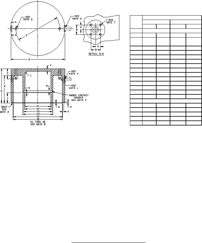
NOTES:
1. Two studs. 1-½-inches (38.10 mm) long threaded ¼-inch (6.35 mm)-20 NC by 1-inch (25.40 mm) with 3/8-inch (9.53 mm)
diameter head. Head of stud shall be drilled and tapped ¼-inch (6.35 mm) deep for No. 6-32 RH machine screw. Use
standard 5/32-inch (3.97 mm) flat washer under screw.
2.
Anode contact groove shall be filled with the following spring: 0.020-inch (0.51 mm) diameter wire wound to give a 0.250-inch
(6.35 mm) O.D. at 35 TPI, 14-¼-inches (361.95 mm) in length (approximate).
3.
Moat shall be filed with a braid to insure continuous braid contact and yet permit firm seating of the cavity on the RF cathode
terminal contact surface.
4.
Two holes. Drill 7/32-inch (5.56 mm) diameter (through), C' bore 3/8-inch (9.53 mm) diameter by 1/8-inch (3.18 mm) deep.
Spot face 1-inch (25.40 mm) diameter by 1/16-inch (1.59 mm) deep.
5.
Two holes. Drill and tap for ¼-inch (6.35 mm)-20 NC screws.
6.
Location of A-N connector - UG-290/U (two connectors 180 degrees apart).
7.
Four holes. Drill and tap for No. 3-48 screws by ¼-inch (6.35 mm) deep.
8.
Cylindrical holes H1 through H6 have axes coincident within 0.001 inch (0.025 mm).
FIGURE 3. Output cavity required for resonant frequency test.
14
For Parts Inquires call Parts Hangar, Inc (727) 493-0744
© Copyright 2015 Integrated Publishing, Inc.
A Service Disabled Veteran Owned Small Business