MIL-PRF-1/1605C
Equipment required:
2 - Cross-guide couplers (30-40 dB directivity)
1 - Slotted line
2 - W aveguide-to-coaxial transitions
1 - Crystal detector
2 - Terminations
1 - Oscilloscope
2 - Coaxial attenuators
1 - Matched load
2 - Variable attenuators
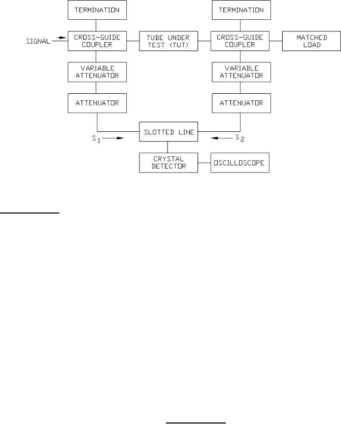
For the measurement of phase sensitivity to voltage change, a setup as shown above shall be used. Both arms 1 and 2
shall be well-matched to minimize reflections. At a fixed frequency and a fixed anode voltage level, the variable
attenuators shall be adjusted to equalize the magnitude of signals S1 and S2. (Oscilloscope comparison of the signal of
S1 and S2 removed, and vice versa, will aid in this step.) The trace shown on the oscilloscope will be a pulse whose
magnitude varies with the position of the probe carriage. The position of the minimum of the standing wave will be
observed by a dip in the oscilloscope signal.
After the minimum position of the standing wave has been located, the operating point of the tube is changed by
reducing the magnitude of the pulse voltage. The new minimum position shall then be located. The phase shift shall be
determined from the difference of the standing wave minimum positions caused by the two voltage levels.
The pulse voltage shall be viewed on an oscilloscope to determine the two voltage levels of the measurement.
The phase sensitivity is determined by dividing the voltage change into the measured phase shift.
FIGURE 2. Phase shift variation.
7
For Parts Inquires call Parts Hangar, Inc (727) 493-0744
© Copyright 2015 Integrated Publishing, Inc.
A Service Disabled Veteran Owned Small Business