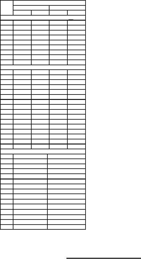
MIL-PRF-1/1605B
NOTES:
Dimensions
1. Reference plane "A" is defined as a plane passing along
Ltr
Inches
Millimeters
the face of the mounting surface as shown.
Min
Max
Min
Max
2. Reference plane "B" is defined as a plane perpendicular
Conformance inspection, part 1 25/
to plane "A" passing through the axis of diameter "ZZ" at
A
4.867
5.241 123.62 133.12
plane "A" and midway between the axes of holes "YY"
B
18.615 18.950 472.82 481.33
at plane "A".
C
---
4.455
---
113.16
3. Reference plane "C" is defined as a plane mutually
N
1.200
1.240
30.48
31.50
perpendicular to planes "A" and "B" passing through the
P
.0595
.0655
1.51
1.66
axis of diameter "ZZ" at reference plane "A".
S
4.960
5.040 125.98 128.02
4. This flange shall mate with a modified M3922/61-002.
V
.500
.520
12.70
13.21
5. This part shall mate with a type "N" plug.
6. These dimensions apply to the axes of diameter "RR" and
Y
.187
---
4.75
---
"PP".
AG
.308
.316
7.82
8.03
7. Terminal for ground adapter.
Conformance inspection, part 2
8. This dimension refers to the axis of diameter "XX".
D
3.632
3.882
92.25
98.60
9. rf input (type "N").
G
.312
---
7.92
---
10. rf output
H
.367
.383
9.32
9.73
11. This section of the tube may be composed of numerous
K
.306
.312
7.77
7.92
laminations, each containing a "V" notch.
L
.855
.895
21.72
22.73
12. Pitch diameter shall accept a class 2 "GO" gauge only.
R
.950
1.050
24.13
26.67
13. Minor diameter shall be not greater than .166 inch
U
.375
---
9.52
---
(4.22 mm).
W
---
3.375
---
85.73
14. This part shall be equivalent to AN-D10050-6.
X
.370
.380
9.40
9.65
15. Getter bushing.
Z
---
3.125
---
79.38
16. Cathode temperature measurement point.
AB
.084
.104
2.13
2.64
17. This part shall be equivalent to AN-D10050-8.
18. For termination.
AD
5.031
5.051
127.79 128.30
19. This part shall mate with an UG-45/U coupling flange.
AE
5.285
5.315
134.24 135.00
20. The axis of this diameter shall lie on reference plane "B"
AJ
1.006
1.050
25.55
26.67
within .020 inch (0.51 mm).
AK
2.342
2.372
59.49
60.25
21. These diameters and mounting holes "W W " shall
AI
.780
---
19.81
---
simultaneously accept a gauge 22.500 inch (571.50 mm)
Nominal dimensions
long with a 2.652 inch (67.36 mm) I. D. with pins as
E
17.125
435.00
shown on "MOUNTING HOLE GAUGE."
F
.235
5.97
22. This surface shall be perpendicular to reference "A" within
J
.850
21.60
.020 inch (0.51 mm).
M
1.050
26.70
23. A centerline created by these pins shall be parallel to
Q
45°
45°
reference plane "A" within .040 inch (1.02 mm) and pass
T
1.000
25.40
through axis of diameter "XX" within .004 inch (0.102 mm).
AA
.063
1.60
24. This surface shall be parallel to a centerline passing
AC
1.750
44.50
through pins "SS" within .025 inch (0.64 mm).
25. This specification uses accept on zero defect sampling
AF
20°
20°
plan in accordance with MIL-PRF-1, table III.
AH
.190-32
4.83-32
AM
22°30'
22°30'
AN
10°
10°
AP
3.410 DIA
86.61 DIA
AQ
.255 DIA
6.48 DIA
AR
.500
12.70
FIGURE 1. Outline drawing of electron tube type 8128 - Continued.
6
For Parts Inquires call Parts Hangar, Inc (727) 493-0744
© Copyright 2015 Integrated Publishing, Inc.
A Service Disabled Veteran Owned Small Business