MIL-PRF-1/1336G
NOTES:
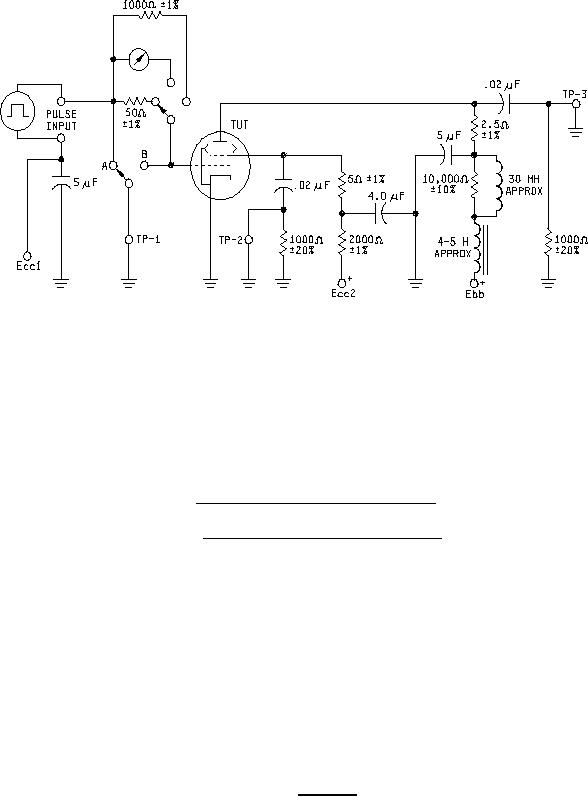
1. Peak anode current (ib) is read on a calibrated oscilloscope across a 2.5-ohm sensing resistor. (TP-3).
2. Peak screen current (ic2) is read on a calibrated oscilloscope across a 5.0-ohm sensing resistor (TP-2).
3. Peak grid current (1) (ic1) is read on either a calibrated oscilloscope across a 50-ohm sensing resistor (TP-1)
or a milliammeter calibrated for peak reading with duty cycle of 0.001).
4. Peak grid current (2) (ic1) is read on either a calibrated oscilloscope across a 1,000-ohm sensing resistor (TP-1)
or a milliammeter calibrated for peak reading with duty cycle of 0.001).
5. egy = e in switch 'B' position. ic (1) = e (switch position A) - e (switch position B)
1
50
e (switch position A) - e (switch position B)
ic1(2) =
1,000
6. Use noninductive resistors.
7. All capacitors shall be mica or paper dielectric with suitable voltage ratings. TP-1, TP-2, TP-3 to suitable wide-band
oscilloscope with low-capacity probe.
FIGURE 4. Test circuit.
9
For Parts Inquires call Parts Hangar, Inc (727) 493-0744
© Copyright 2015 Integrated Publishing, Inc.
A Service Disabled Veteran Owned Small Business