MIL-PRF-1/1336G
NOTES:
1.
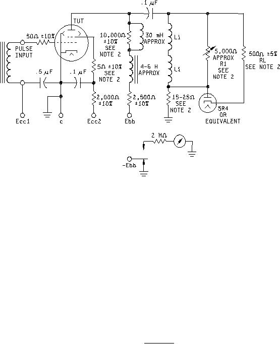
L1 = 5.5 mH approximately (Sickles SC101A, or equivalent.)
2.
Use noninductive resistor.
3.
Use paper or mica dielectric capacitors.
4.
Anode current is read on a microammeter in series with the negative lead of the power supply and is shown at point E.
The 2-megohm resistor and meter are inserted in the negative lead as shown for the anode current test only. L1 and R1
adjusted for the voltage backswing = 50 percent of forward swing.
FIGURE 3. Test circuit.
8
For Parts Inquires call Parts Hangar, Inc (727) 493-0744
© Copyright 2015 Integrated Publishing, Inc.
A Service Disabled Veteran Owned Small Business