MIL-DTL-24251F
Tube
A
B
R
outline
in
mm
in
mm
in
mm
±.001
±0.25
±.010
±0.25
±.031
±0.79
1.100
27.94
T3
.380
9.65
1.400
35.56
.080
2.03
1.625
41.28
1.125
28.58
T5 1/2
.730
18.54
1.500
38.10
.156
3.96
2.000
50.80
1.125
28.58
1.562
39.67
T6 1/2
.840
21.34
.281
7.14
2.000
50.80
2.437
61.90
1.750
44.45
2.062
52.37
2.312
58.72
2.500
63.50
T9
1.150
29.21
.400
10.16
2.688
68.28
2.750
69.85
3.062
77.77
3.250
82.55
2.937
74.60
3.312
84.12
T11
1.410
35.81
.470
11.94
3.687
93.65
4.062
103.17
2.375
60.33
2.500
63.50
2.625
66.68
2.750
69.85
2.938
74.63
3.000
76.20
T12
1.560
39.62
.500
12.70
3.125
79.38
3.250
82.55
3.312
84.12
3.500
88.90
3.688
93.68
3.750
95.25
3.875
98.43
4.125
104.78
T14
1.830
46.48
.590
14.99
4.813
122.20
T16
2.050
52.07
4.175
106.05
.650
16.51
4.750
120.65
NOTES:
1. Dimensions are in inches.
2. Millimeters are in parentheses.
3. Metric equivalents are given for general information only and are based upon 1.00 inch = 2.54 mm.
4. Material: Tool steel, hardened to 56-61C.
5. Finish: Hard chrome plate.
6. Mounting method optional (screw and pins).
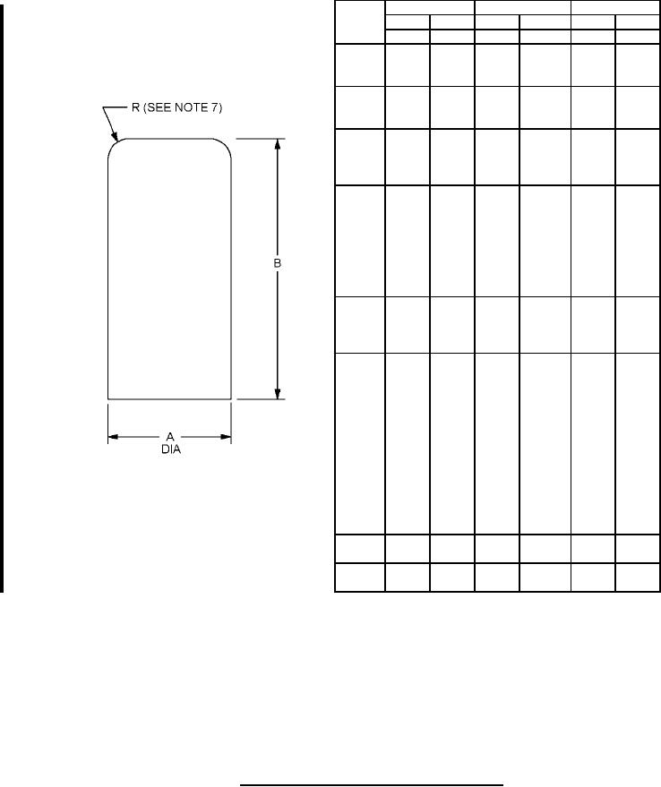
7. Radius shall be blended smoothly into A diameter.
FIGURE 1. Test slugs for installation and removal force tests.
8
For Parts Inquires call Parts Hangar, Inc (727) 493-0744
© Copyright 2015 Integrated Publishing, Inc.
A Service Disabled Veteran Owned Small Business