MIL-PRF-1/970F
Dimensions
Ltr
Inches
Millimeters
Min
Max
Min
Max
Conformance inspection, part 1 5/
A
6.580
6.640 167.13
168.66
K
---
3.008
---
76.40
P
---
.190
---
4.83
Q
.165
.195
4.19
4.95
R
.347
.377
8.81
9.58
T
---
.810
---
20.57
Conformance inspection, part 2
C
2.490
2.510
63.25
63.75
E
2.240
2.260
56.90
57.40
L
3.203
3.233
81.36
82.12
M
1.703
1.733
43.26
44.02
N
---
1.508
---
38.30
Reference dimensions
B
4.12
104.65
D
.81
20.57
F
.19
4.83
G
2.62
66.55
H
.25
6.35
J
.12
3.05
S
.22
5.59
NOTES:
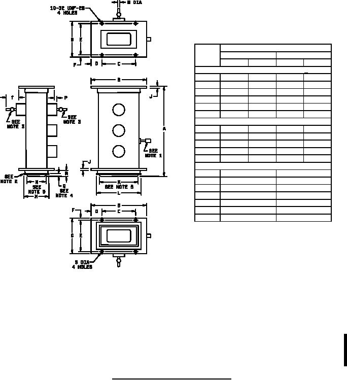
1. Exhaust tube shall not extend beyond flange; more than .25 inch (6.35 mm).
2. Gasket in accordance with Drawing 189-JAN: Gasket to be securely attached.
3. Ignitor electrode may be mounted in either of positions shown.
4. Dimension Q shall be measured prior to the attachment of the gasket to the tube.
5. The edges of the input window plate shall have either a radius of .020 inches (.51 mm) minimum or a 45 chamfer of .020
inch (.51 mm) minimum.
6. Mount either series or shunt mount may be used. If series mount is used, mount shall be in accordance with Drawing 153-
JAN or equivalent.
7. This specification sheet uses accept on zero defect sampling plan in accordance with MIL-PRF-1, table III.
FIGURE 1. Outline drawing of electron tube type 1B58A.
4
For Parts Inquires call Parts Hangar, Inc (727) 493-0744
© Copyright 2015 Integrated Publishing, Inc.
A Service Disabled Veteran Owned Small Business