MIL-PRF-1/877E
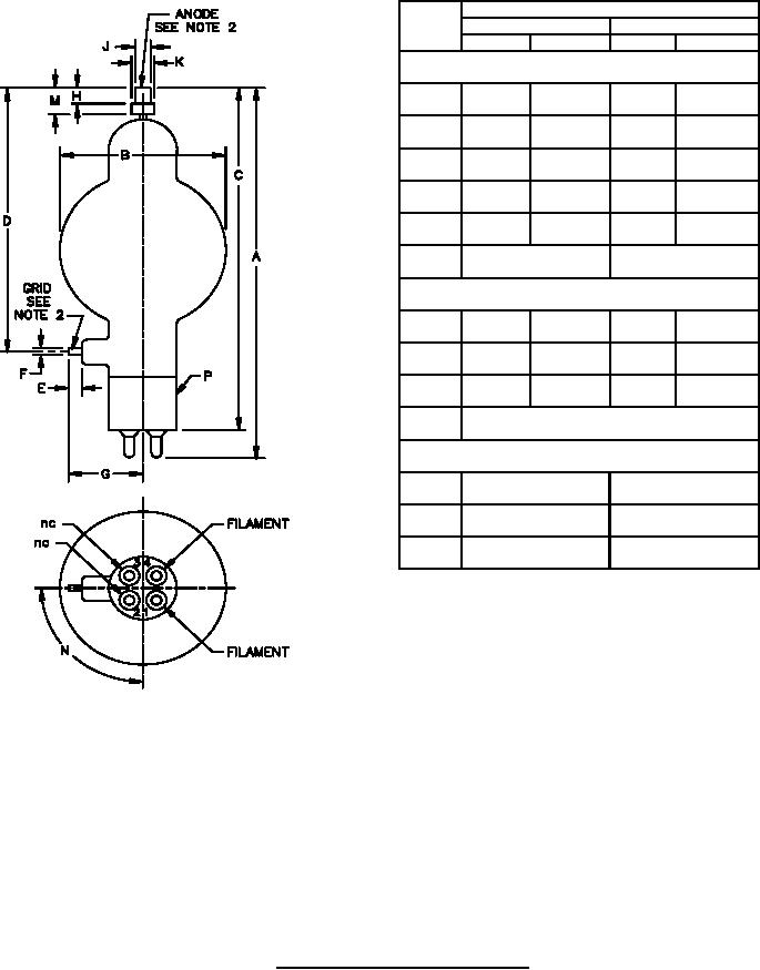
Dimensions
Ltr
Inches
Millimeters
Min
Max
Min
Max
Conformance inspection, part 2
A
7.250
7.750
184.15
196.85
3.188
80.98
B
---
---
5.000
5.500
127.00
139.70
D
.250
6.35
E
---
---
1.250
1.500
31.75
38.10
G
N
80°
100°
Conformance inspection, part 3 (see note 1)
6.625
7.125
168.28
180.98
C
.055
.061
1.40
1.55
F
.350
.365
8.89
9.27
J
Base: A4-10 (EIA)
P
Reference dimensions
H
.328
8.33
KD
.500
12.70
M
.563
14.30
NOTES:
1. These dimensions shall be checked annually with the following sampling plan:
where c2 represents the total failures for the
n1 = 4
c1 = 0
n2 = 4
c2 = 0;
first and second samples combined.
In case of failure after double sampling, the failing dimension(s) shall become conformance inspection, part 2, for three
successful consecutive submissions, at which time the test may revert to the conformance inspection, part 3 basis.
2. Heat radiating connectors HR-2 (grid) and HR-6 (anode) or equivalent, are recommended for all applications.
FIGURE 1. Outline drawing of electron tube type 100TH.
3
For Parts Inquires call Parts Hangar, Inc (727) 493-0744
© Copyright 2015 Integrated Publishing, Inc.
A Service Disabled Veteran Owned Small Business