MIL-PRF-1/66C
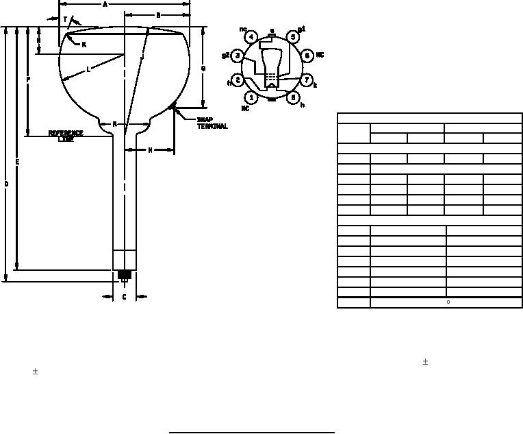
Dimensions
Ltr
Inches
Millimeters
Min
Max
Min
Max
Conformance inspection, part 2
A
6.875
7.125
174.63
180.98
B
See note 1
C
1.313
1.427
33.35
36.25
D
12.875 13.625
327.03
346.08
F
5.500
6.000
139.70
152.40
G
3.693
4.193
93.80
106.50
Reference dimensions (see note 5)
E
12.687
322.25
H
2.625
66.68
J
24.000 R
609.60 R
K
.250 R
6.35 R
L
3.500 R
88.90 R
N
1.375
34.93
R
3.125
79.38
T
5
NOTES:
1. The minimum useful screen radius shall not be less than 3.00 inches (76.20 mm).
2. The bulb shall be a J56D or J56R type.
3. Applies to entire length of neck below reference line. The reference line is determined by point where gage 1.430 . 003 inches
(36.32 0.08 mm) inside diameter and 2 inches (50.80 mm) in length will stop against bulb body.
4. The base shall be a medium shell octal 8-pin (B8-11) type or a medium long shell octal 8-pin type (this is identical with the
medium shell octal 8-pin type except that the shell is 1.375 inches (34.93 mm) high nominal) or a small wafer octal with sleeve
8-pin (B8-26) type.
5. Reference dimensions are for information only and are not required for inspection purposes.
FIGURE 1. Outline drawing for electron tube type 7BP7A.
Custodians:
Preparing activity:
Army - CR
DLA - CC
Navy - EC
Air Force - 11
(Project 5960-3470)
DLA - CC
Review activities:
Army - CR4
Navy - AS, CG, MC, OS, SH
Air Force - 17, 99
5
For Parts Inquires call Parts Hangar, Inc (727) 493-0744
© Copyright 2015 Integrated Publishing, Inc.
A Service Disabled Veteran Owned Small Business