MIL-PRF-1/211G
Alternate base, 4 pin, metal shell with ceramic wafer insert.
Dimensions
Ltr
Minimum
Maximum
Conformance inspection, part 2
A
4.000 (101.60)
4.375 (111.13)
B
1.313 (33.35)
1.438 (36.53)
C
3.404 (86.46)
D
1.437 (36.50)
1.687 (42.85)
E
1.100 (27.94)
1.300 (33.02)
F
0.310 (7.87)
0.440 (11.18)
G
0.045 (1.14)
0.051 (1.30)
Conformance inspection, part 3
(see note 5)
H
Base: A4-5 (see note 2)
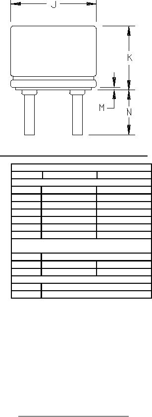
J
1.137 (28.88)
1.165 (29.59)
K
0.820 (20.83)
0.850 (21.59)
Reference dimensions
M
0.032 (0.81)
N
0.563 (14.30)
NOTES:
1. For pin alignment, use gage GA4-1.
2. A metal shell base with ceramic wafer insert may be used.
3. Deviation of centerline of anode lead from centerline of base shall not exceed 0.125 (3.18 mm).
4. Deviation of centerline of grid lead from centerline of base shall not exceed 3°.
5. These dimensions shall be tested annually.
FIGURE 1. Outline drawing of electron tube type 3C24 - Continued.
4