MIL-PRF-1/208G
Dimensions
Ltr
Minimum
Maximum
Conformance inspection, part 1
A
1.054 (26.77)
1.070 (27.18)
B
0.995 (25.27)
1.005 (25.53)
L
1.125 (28.58)
1.250 (31.75)
P
0.670 (17.02)
0.675 (17.15)
U
1.250 (31.75)
1.375 (34.93)
Conformance inspection, part 2
M
0.093 (2.36)
N
0.125 (3.18)
Q
0.010 (0.25)
R
0.040 (1.02)
S
0.070 (1.78)
T
0.070 (1.78)
V
1.094 (27.79)
W
0.500 (12.70)
Y
0.938 (23.83)
Conformance inspection, part 3
(periodic check)
C
0.875 (22.23)
D
0.719 (18.26)
0.781 (19.84)
H
0.248 (6.30)
0.252 (6.40)
J
0.234 (5.94)
0.266 (6.76)
Nominal dimensions (see note 2)
E
0.672 (17.07)
F
0.500 (12.70)
G
0.436 (11.07)
X
0.188 (4.78)
NOTES:
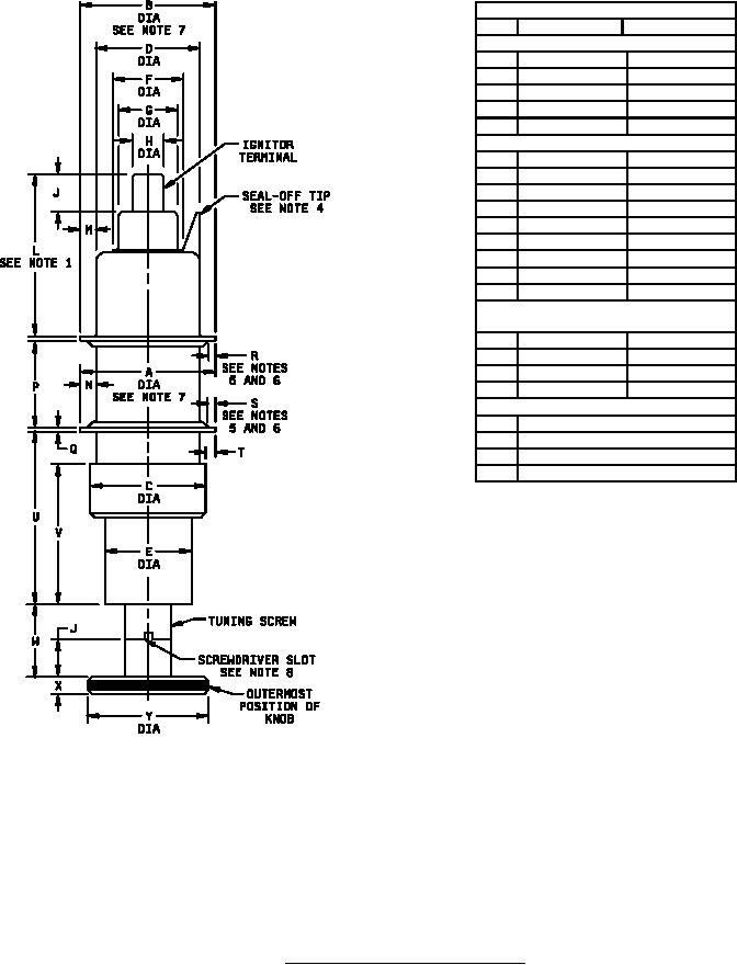
1. Dimension L may be increased 0.03 inch (0.76 mm) by solder.
2. Dimensions without tolerances are for information and are not required for inspection purposes.
3. The acceptance level for the combined mechanical defectives in conformance inspection, part 1, shall be 1.0 percent.
4. Seal-off tip is optional and must not extend above dimension J base line.
5. Contact portion of disk measured radially must be free from splits or tears and must be smooth and flat to
the extent controlled by dimension P.
Figure I. Outline drawing of electron tube type 1B27.
5
For Parts Inquires call Parts Hangar, Inc (727) 493-0744
© Copyright 2015 Integrated Publishing, Inc.
A Service Disabled Veteran Owned Small Business