MIL-PRF-1/208G
TABLE I. Testing and Inspection - Continued.
5. The test shall be made in the equipment specified in note 7. The tube shall cover a tuning range from less
than 2,600 MHz to more than 3,000 MHz. No tube shall require less than five complete turns of the tuning
screw to cover this range. As the tuning screw is turned through its complete range, the transmitted power
shall show only one dip.
6. After a shelf life of 7 days, mount the tube in cavity as shown on Drawing 263-JAN. The peak leakage
power shall be averaged over the pulse length. Two measurements of the leakage power shall be made.
The first shall be made with ignitor current at 100 µA dc and the second, with no ignitor current.
7. The intrinsic Q shall be measured in the equipment depicted on figures 2 and 3, at a frequency of 3,000
MHz ± 1 percent. Ten feet of 50 Ω lossy cable shown (see figure 4) shall be used as a termination in
order to provide a matched output. The 6- to 8- dB loss in the termination is sufficient to eliminate the
mismatch of the transitions. With the attenuator flap raised completely out of the guide, the tube shall be
tuned to resonance and VSWR measurements made, covering a band of 8 to 10 MHz centered at the
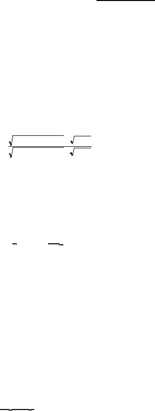
resonant frequency. The value for r′, which is the VSWR at the frequency for which the normalized
reactance of the tube is equal to unity, is given by the equation:
(2 R 2 + 2 + 1 / R) + 1 +
R2 + 1
r′ =
(2 R 2 + 2 + 1 / R) + 1 -
R2 +1
Where:
R = effective shunt resistance across the guide (introduced by the tube)
ro, the VSWR at resonance, is given by ro = (1/R) +1
A curve of r' versus ro is shown on figure 5. After determining r' from figure 5, the frequencies f1 and f2, corresponding to
values of normalized reactance equal to unity, are obtained from the curve of VSWR versus frequency.
A sample of this determination is shown on figure 6. The intrinsic Q is then determined by:
QO =
1
x
fO__
R
(f1- f2)
Where:
fO = resonant frequency of the tube.
f1 = upper frequency at which normalized reactance equals unity.
f2 = lower frequency at which normalized reactance equals unity.
R = effective shunt resistance of the tube.
The intrinsic Q can also be measured by a relative method in the equipment as shown on figure 3. The ratio
of power in the load with the TR detuned to the power with the TR tuned is:
P = (1 + 1/2R)2
Where:
R = effective shunt resistance of the tube.
A plot of P versus 1/R is shown on figure 7. If the intrinsic Q and R are measured for a TR tube in the test
equipment as above, the Q of any other TR tube may be found by determining R and inserting it in the
formula:
Q = (QO1) (R1)
R
Where:
QO1 and R1 are the constants for the calibrated tube.
3
For Parts Inquires call Parts Hangar, Inc (727) 493-0744
© Copyright 2015 Integrated Publishing, Inc.
A Service Disabled Veteran Owned Small Business