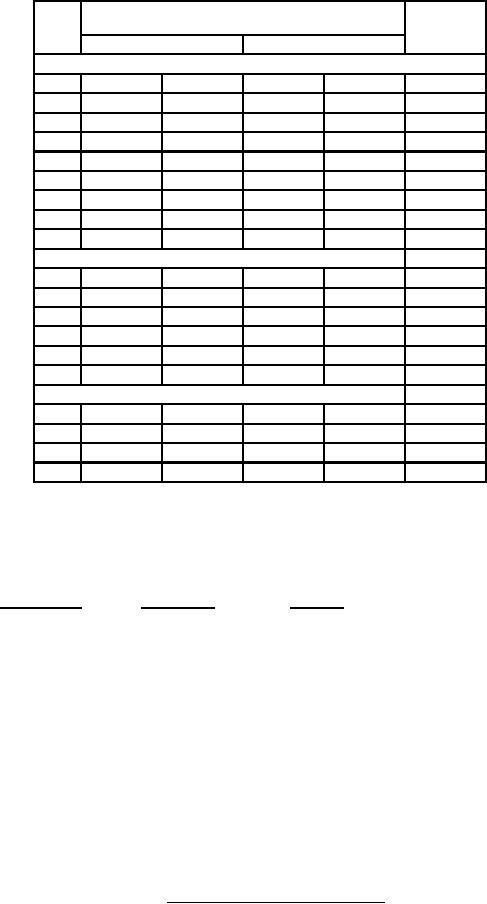
MIL-PRF-1/1766B
Dimensions
Notes
LTR
Millimeters
Inches
Conformance inspection, part 2
Min
Max
Min
Max
A
25.15
25.65
0.990
1.010
2
C
18.80
19.05
0.740
0.750
2
D
1.19
1.35
0.047
0.053
2
E
5.00
5.26
0.197
0.207
2
F
34.80
36.32
1.370
1.430
G
29.21
30.61
1.150
1.205
K
9.27
11.05
0.365
0.435
L
19.05
21.59
0.750
0.850
Conformance inspection, part 3
1
B
16.26
16.76
0.640
0.660
H
17.14
19.68
0.675
0.775
J
3.18
4.95
0.125
0.195
M
1.02
1.90
0.040
0.075
N
5.08
6.86
0.200
0.270
P
0.18
0.33
0.007
0.013
Electrode contact dimensions
5
AA
2.03
----
0.080
----
3, 4
AB
6.98
9.14
0.275
0.360
3, 4
AC
31.24
34.04
1.230
1.340
4
AD
24.89
27.94
0.980
1.100
4
NOTES:
1. Use a sample of 4.
2. Gold plate (note a applies).
3. Eccentricity of contact surfaces shall be gaged from the center line of reference and shall be as follows (note a applies):
Contact surface
TIR maximum
Reference
Anode (A)
0.040 (1.02)
Cathode (E)
Grid (C)
0.020 (0.51)
Cathode (E)
4. Dimensions of contact surfaces shall apply throughout entire contact area.
5. Dimensions in electrode contact area table are for conformance inspection, part 2 purposes only, and are not intended for inspection
purposes.
6. This surface shall not be used for clamping or locating.
7. Eccentricity of backup ceramic to anode (A) 0.031 (0.79 mm) maximum; to be measured with EIMAC gage G-2285, or equivalent.
FIGURE 1. Outline drawing of electron tube type 8980 - Continued.
5