MIL-PRF-1/1766B
TABLE I. Testing and Inspection.
3/ Measure in test fixture in accordance with DSCC Drawing D76025.
4/ Measure in stalo cavity (magnitostriction resonator Raytheon part number 401509-1, or equivalent) in accordance with figure 2. The
output coupling loops (2) shall be set and locked at the 45º position. Anode supply shall be a well regulated 150 V dc (±5 percent)
supply and heater supply shall be a well regulated 6.0 V dc (±0.1 V) supply. The anode current shall be adjusted to be within 20 to 30
mA dc by adjustment of an external cathode bias resistor. Output from one of two coupling loops of the stalo assembly shall be 20.0
mW minimum. All tuning adjustments are to be used to the fullest extent to make the tubes operate in accordance with the
requirements. W ith the AFC control set in the electrical center of its range, and with all tuning rods locked in the position, the power
will be measured at 2.67, 2.80, and 2.93 GHz, observing that throughout the tuning range between the limit frequencies the power
shall not drop below 20 mW . The maximum cathode current shall not at any time exceed 40 mA dc.
5/ Grid-anode resonance. Test in cavity in accordance with DSCC Drawing D76024. Cavity shall resonate at 2,022 ± 2.0 MHz with
tuning slug in accordance with DSCC Drawing C76022 at TA = 25 ± 5ºC.
Grid-cathode resonance. Test in cavity in accordance with DSCC Drawing C76026. Cavity shall resonate at 4,420 ± 5.0 MHz with
tuning slug in accordance with DSCC Drawing C76022.
W hen plotted on graphs of resonant frequency versus grid-anode capacitance and resonant frequency versus grid-cathode (input)
capacitance, the tube under test shall be represented by a point within a parallelogram whose four corners are located by the following
points:
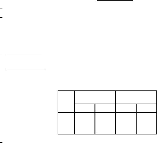
Capacitance (pF)
Frequency (MHz)
Points
C-gp
C-gk
F-gp
F-gk
1,386
1,252
1.3
1.95
1
1,446
1,282
1.3
1.95
2
1,264
1,224
1.7
2.35
3
1,324
1,254
1.7
2.35
4
6/ All DSCC drawings are available from Defense Supply Center Columbus, DSCC-VAT, Columbus, Ohio 43216-5000.
3