MIL-PRF-1/1766B
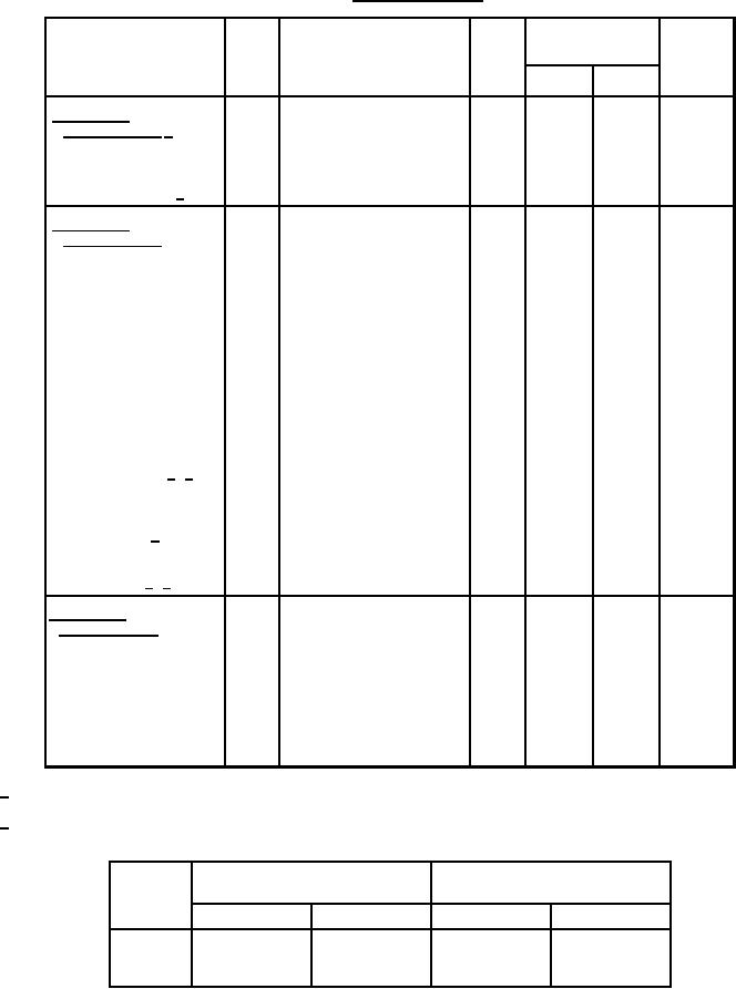
TABLE I. Testing and Inspection.
Limits
Inspection
Method
Conditions
Unit
Symbol
Min
Max
Conformance
inspection, part 1 1/
mA
590
530
If
Heater current
1301
----
----
----
----
Constant grid voltage 2/
----
Conformance
inspection, part 2
mA dc
40.0
6.0
Ib
Ec = -6.0 V dc
1256
Electrode current (1)
(anode)
mA dc
40.0
10.0
Ib
Eb = 75 V dc;
1256
Electrode current (2)
Ec = Ek = 0 V dc
(anode)
V dc
-7.5
-2.0
Ec
Eb = 150 V dc;
1261
Electrode voltage (grid)
Ec/Ib = 15 mA dc
----
28.0
14.0
Mu
Eb = 75 V dc; Ec = 0 V dc
1316
Amplification factor
µmhos
10,000
2,500
Sm
Eb = 75 V dc; Ec = 0 V dc
1306
Transconductance
1.70
1.30
Cgk
1331
Direct-interelectrode 3/ 6/
pF
2.35
1.95
Cgp
capacitance (grounded
pF
0.04
----
Cpk
cathode connection)
pF
----
20.0
Po
Ebb = 150 V dc;
1236
Power oscillation 4/
mW
Rk/Ik = 25 mA dc
----
----
----
----
Cold resonance 5/ 6/
----
Conformance
inspection, part 3
----
----
----
----
Group C; heater standby; Ef =
----
Life test
6.0 V; no other voltages applied;
t = 500 hours
Life-test end point :
mW
----
15.0
Po
1236
Power oscillation
1/ All tests listed under conformance inspection, part 1, shall be performed at the conclusion of the holding period. Acceptance is based
upon zero failures.
2/ Constant grid voltage tests will be performed by means of a curve tracer. Anode voltage (eb) shall vary between 0 and 180 V. Limits
for constant grid voltages are defined as follows:
Grid voltage = 0 V
Grid voltage = -6 V
eb
ib = ma (min)
ib = ma (max)
ib = ma (min)
ib = ma (max)
----
10.0
40.0
----
75 V
33.0
----
----
2.0
150 V
40.0
6.0
180 V
30.0
80.0
2