MIL-PRF-1/1717C
TABLE I. Testing and inspection - Continued.
6/ Operation at this altitude is possible in a suitably designed circuit.
7/ In all electrical tests involving applications of heater voltage, sufficient conduction, convection, or forced-air cooling
may be provided for all seals to limit temperatures.
8/ Voltage shall be 60 Hz ac applied between anode and grid. No other voltages shall be applied. There shall be no
evidence of failure as indicated by arc-over. This is not a destructive test.
9/ Other tube contact configurations may be used provided the tube contact area remains unchanged and the socket,
jig, or cavity gives equal performance. Mounting of the socket, jig, or cavity may be at the option of the manufacturer.
10/ Grid-anode resonance. Test in cavity in accordance with Drawing 278-JAN. Cavity shall resonate at 1,354 ± 2 MHz
with tuning slug in accordance with Drawing 277-JAN at TA = 25°C ± 5°C.
Grid-cathode resonance. Test in cavity in accordance with Drawing 283-JAN. Cavity shall resonate at 1,719 ± 2
MHz with tuning slug in accordance with Drawing 277-JAN at TA = 25°C ± 5°C.
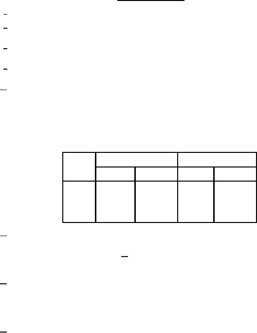
W hen plotted on graphs of resonant frequency versus grid-anode capacitance and resonant frequency versus grid-
cathode (input) capacitance, the tube under test shall be represented by a point within a parallelogram whose four
corners are located by the following points:
Capacitance (pF)
Frequency (MHz)
Points
Cgp
Cgk
Fgp
Fgk
1760
2010
7.0
1.85
1
1800
2040
7.0
1.85
2
1720
1940
9.0
2.10
3
1760
1970
9.0
2.10
4
11/ This test shall be performed during the initial production and once each succeeding 12-calendar months in which
there is production. An accept on zero defect sampling plan shall be used, with the sample of three tubes with an
acceptance number of zero failures. In the event of failure, the test will be made as a part of conformance inspection,
part 2, with an acceptance level of 6.5 (see 19/). The regular "12-calendar month" sampling plan shall be reinstated
after three consecutive samples have been accepted. None of the testing shall be considered as destructive except
in case of failure.
12/ The applied voltage pulse shape shall be measured with a noninductive resistor of 1,150 ohms ± 2 percent inserted in
place of the tube. The pulse shape shall be: tp = 3.0 µs ± 10 percent, tr = 0.4 µs maximum, and tf = 0.7 µs
maximum. The pulse repetition rate (prr) shall be adjusted so that Du = 0.0025 ± 5 percent with the above measured
pulse length. Test in cavity in accordance with Drawing 279-JAN. The cavity shall be connected to a load with a
VSW R less than 1.5/1. The oscillator output coupling and the grid or cathode resistor may be adjusted for maximum
power output.
13/ Test shall be conducted in power amplifier cavity as shown on figure 2, or equivalent. Driving power is defined as the
net power delivered to the amplifier cavity input terminals and the reflected power shall be subtracted from the incident
power to obtain the net driving power. The output tuning shall be adjusted for maximum power output.
4
For Parts Inquires call Parts Hangar, Inc (727) 493-0744
© Copyright 2015 Integrated Publishing, Inc.
A Service Disabled Veteran Owned Small Business