MIL-PRF-1/1660C
TABLE I. Testing and inspection - Continued.
1/
The transit time heating effect of the cathode shall be compensated by a reduction in heater voltage after dynamic operation of
the tubes has started. The back heating is a function of frequency, grid current, grid bias, anode current, duty cycle, and
circuit design and adjustment. There is an optimum heater voltage that will maintain the cathode at the correct operating
temperature for a particular set of operating conditions. A maximum variation of ± 5 percent from optimum is permitted. No
reduction in heater voltage is required up to and including 500 MHz.
2/
W here emphasis is placed on long and reliable life, the filament voltage can safely be lowered to 6.0 volts, provided the line
voltage is regulated better than ± 2 percent.
3/
Regulation, or series-anode-supply impedance, or both, shall limit the instantaneous peak current, with the tube considered as
a short circuit, to a maximum of 10 times the specified maximum current rating.
4/
The maximum instantaneous peak grid-cathode voltage shall be within the range of +250 to -750 volts.
5/
Sufficient conduction, convection, and forced air cooling shall be provided to limit the envelope and anode shank temperatures
to the specified maximum value under all operating conditions. Reliability will be seriously impaired if this maximum is
exceeded. W here emphasis is placed on long and reliable life, lower temperatures shall be used.
6/
All tests listed under conformance inspection, part 1, shall be performed at the conclusion of the holding period.
7/
Sufficient conduction, convection, and forced-air cooling shall be used in all electrical tests involving application of heater
voltage to maintain the anode shank and seal temperatures within the specified maximum values.
8/
Other tube contact configuration may be used provided the tube contact area remains unchanged, and the socket, jig, or cavity
gives equal performance. The socket, holding fixture, or cavity shall be rigidly secured to the test platform.
9/
Measure in socket in accordance with DSCC Drawing No. 68017.
10/ Grid-anode resonance. Cavity shall resonate at 4,980 MHz ± 10 MHz in accordance with DSCC Drawing No. 67032.
Grid-cathode resonance. Cavity shall resonate at 1,377 MHz ± 2 MHz in accordance with DSCC Drawing No. 67033.
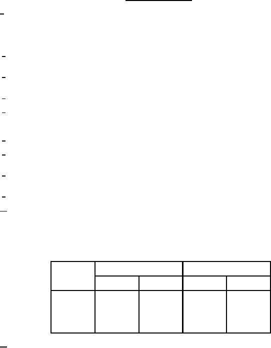
W hen plotted on graphs of resonant frequency versus grid-anode capacitance and resonant frequency versus grid-cathode
capacitance, the tube under test shall be represented by a point within a parallelogram whose four corners are located by the
following points:
Capacitance (pF)
Frequency (MHz)
Points
Cgp
Cgk
Fgp
Fgk
1,461
1,465
7.0
2.95
1
1,421
1,425
7.0
2.95
2
1,440
1,380
9.0
3.25
3
1,400
1,340
9.0
3.25
4
11/ The applied voltage pulse shape shall be tp = 0.5 µs ± 10 percent, tr = 0.05 µs and tf = 0.1 µs maximum. The pulse
repetition rate shall be adjusted so that Du = 0.001 ± 5 percent with the above specified pulse length. Test in cavity
Microwave Control Corp. Model T-104, or equivalent. The cavity and circuit connections are shown on figures 2 and
3. The grid drive is measured with the heater and bias voltage "on" and the anode voltage "off". Under these
conditions the peak positive voltage with respect to the cathode should be egk = 25 volts maximum.
4
For Parts Inquires call Parts Hangar, Inc (727) 493-0744
© Copyright 2015 Integrated Publishing, Inc.
A Service Disabled Veteran Owned Small Business