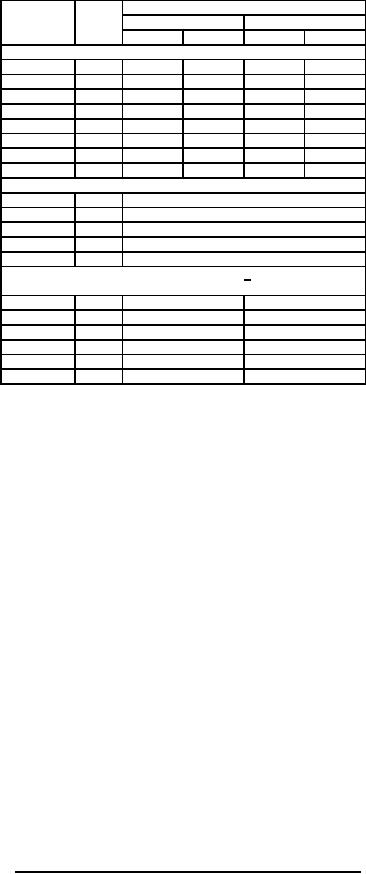
MIL-PRF-1/1392D
Dimensions
Type
Ltr
Inches
Millimeters
Min
Max
Min
Max
Conformance inspection, part 2
All
A
4.844
5.030
123.04
127.76
All
B
2.125
---
54.98
---
All
C
1.318
1.432
33.48
36.37
P14A
D
10.750
11.500
273.05
292.10
P7A, P25
D
10.750
11.125
273.05
282.58
All
F
3.625
3.749
92.08
95.22
All
G
1.188
1.562
30.18
39.67
°
10°
°
10°
All
N
Conformance inspection, part 3 (periodic check)
P7A, P25
Q
Base: B8-11, B8-65, B8-26
P14A
Q
Base: B8-11 or B8-65
P7A, P25
R
Envelope: J39-½L, J39-½F
P14A
R
Envelope: J39-½L
All
S
Contact: J1-22
Reference dimensions 7/
All
E
1.000
25.40
All
J
24.000 Rad
609.60 Rad
All
K
10.000 Rad
254.00 Rad
All
L
.125 Rad
3.18 Rad
All
M
.906 Rad
23.01 Rad
All
P
.812
20.62
NOTES:
1. Unless otherwise specified, all dimensions are in inches.
2. Minimum useful screen radius.
3. Determined by point where gauge G124 will stop.
4. Applies to entire length of neck below reference line.
5. Axis of contact terminal shall be normal to bulb surface.
6. Allowable deviation from true position on center line.
7. Reference dimensions are for information only and are not required for inspection purposes.
FIGURE 1. Outline drawing of electron tube types 5FP7A, 5FP14A, and 5FP25 - Continued.
7
For Parts Inquires call Parts Hangar, Inc (727) 493-0744
© Copyright 2015 Integrated Publishing, Inc.
A Service Disabled Veteran Owned Small Business