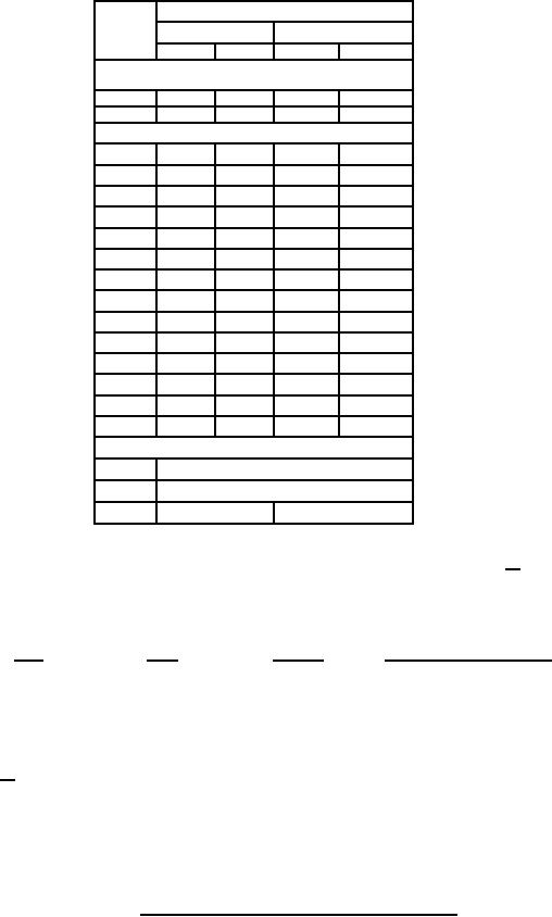
MIL-PRF-1/1371J
Dimensions
Ltr
Inches
Millimeters
Min
Max
Min
Max
Conformance inspection, part 1
(see note 1)
K
.100
.180
2.54
4.57
N
2.985
3.015
75.82
76.58
Conformance inspection, part 2
A
---
5.895
---
149.73
B
3.945
4.340
100.20
110.24
C
---
1.555
---
39.50
D
2.985
3.015
75.82
76.58
E
2.410
2.530
61.21
64.26
F
---
.313
---
7.95
G
.980
1.355
24.89
34.42
H
.093
---
2.36
---
J
.520
.570
13.21
14.48
M
---
.375
---
9.53
P
3.235
3.265
82.17
82.93
R
3.245
3.305
82.42
83.95
S
---
1.081
---
27.46
W
---
.469
---
11.91
Reference dimensions
135°
T
90°
U
V
1.500
38.10
NOTES:
1. The acceptance level for dimensions listed under conformance inspection, part 1, shall be 1.0 (see 18/).
2. Reservoir and heater terminals shall be identified and marked on tube base as specified herein.
3. Insulated leads to be on 10.00 inch (254.0 mm) ± 1.00 inch (25.4 mm) centers.
4. Lead identification terminal lugs and insulation sleeving (in accordance with MIL-I-3190) shall be as follows.
See note 5 for inspection procedures.
Lead
Color
Sleeving
Terminal lugs clearance hole
H = Heater
Yellow
H-A-I or H-B-I
.25 stud
R = Reservoir
Red
H-A-I or H-B-I
#10 stud
5. Dimensions shall be checked during the initial production and once each succeeding 12-calendar months in which there is
production. An accept on zero defect sampling plan shall be used, with sample of three tubes with an acceptance number
of zero. In the event of failure, the test will be made as a part of conformance inspection, part 2, with an acceptance level
of 6.5 (see 18/). The "12-calendar month" sampling plan shall be reinstated after three consecutive samples have been
accepted.
FIGURE 1. Outline drawing of electron tube type 7322 - Continued.
6
For Parts Inquires call Parts Hangar, Inc (727) 493-0744
© Copyright 2015 Integrated Publishing, Inc.
A Service Disabled Veteran Owned Small Business