MIL-PRF-1/1350G
Dimensions
Ltr
Inches
Millimeters
Min
Max
Min
Max
Conformance inspection, part 2
A
3.458
3.832
87.83
97.33
C
3.485
3.515
88.52
89.28
E
1.615
1.630
41.02
41.40
F
.655
.719
16.64
18.26
K
1.056
1.219
26.82
30.96
M
.559
.573
14.20
14.55
W
.056
.062
1.42
1.57
X
.120
.127
3.05
3.23
Conformance inspection, part 3
(see note 1)
B
3.968
4.032
100.79
102.41
G
1.395
1.645
35.43
41.78
H
1.468
1.532
37.29
38.91
J
.593
.657
15.06
16.69
L
.438
.562
11.13
14.27
N
.400
---
10.16
--
P
---
.125
---
3.18
T
.250
---
6.35
---
V
.220
---
5.59
---
Reference dimensions
51°
51°
D
Q
.125
3.18
52°
52°
R
S
.125
3.18
U
.250
6.35
Y
1.000
25.40
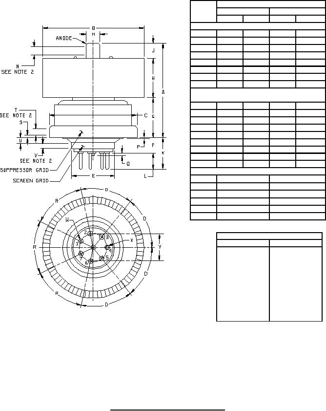
PIN CONNECTIONS
Pin No.
Element
k
1
g1
2
h
3
k
4
h
5
g1
6
k
7
int con
Center pin
g2
Lower ring
g3
Upper ring
a
Cap
NOTES:
1. Dimensions shall be checked yearly. An accept on zero defect sampling plan shall be used, with sample of three tubes
with an acceptance number of zero. In the event of failure, the test will be made as a part of conformance inspection, part
2, acceptance level of 6.5 (see 6/). The yearly sampling plan may be reinstated after three consecutive samples have been
accepted.
2. Contact surface shall be confined to this area.
FIGURE 1. Outline drawing of electron tube type 8295A.
4
For Parts Inquires call Parts Hangar, Inc (727) 493-0744
© Copyright 2015 Integrated Publishing, Inc.
A Service Disabled Veteran Owned Small Business