MIL-PRF-1/1342C
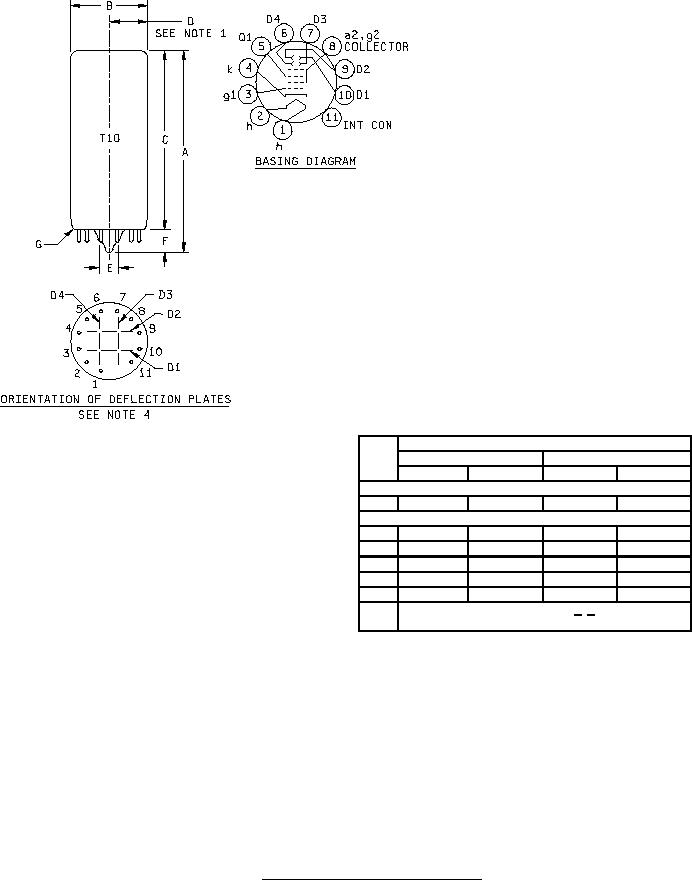
Dimensions
Ltr
Inches
Millimeters
Min
Max
Min
Max
Conformance inspection, part 2
A
---
4.060
---
103.12
Conformance inspection, part 3
B
1.190 DIA
1.310 DIA
30.23 DIA
33.27 DIA
C
3.440
3.680
87.38
93.47
D
0.500 R
---
12.70 R
---
E
---
0.312 DIA
---
7.92 DIA
F
---
0.375
---
9.53
G
Base: E 11-22 2/ 3/
NOTES:
1. Useful screen radius.
2. JEDEC designation.
3. Base pin alignment shall be gauged by means of a flat-plate gauge .25 inch (6.35 mm) thick, with 12 holes .0520 ± .0005
inch (1.30 ± .01 mm) diameter and on a circle 0.6870 ± .0005 inch (17.45 ± .01 mm) diameter and 1 hole .3750 inch
(9.53 mm) diameter concentric with pin circle. Chordal distance between any two adjacent pin holes shall be .1778
± .0005 inch (4.52 ± .01 mm). Gauging procedure 1, as specified in JEDEC publication JO-G2-2, shall apply.
4. Orientation of deflection plates is shown as viewed from underside of base.
FIGURE 1. Outline drawing of electron tube type 1EP1.
4