MIL-PRF-1/1331F
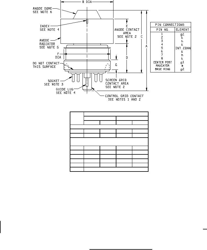
Dimensions
Ltr
Inches
Millimeters
Min
Max
Min
Max
Conformance inspection, part 2
A
2.224
2.404
56.49
61.06
C
1.710
1.850
43.43
46.99
Conformance inspection, part 3
(periodic check) (see note 7)
B
1.610
1.640
40.89
41.66
D
.750
.810
19.05
20.57
E
.710
.790
18.03
20.07
F
---
1.406
---
35.71
G
.187
---
4.75
---
H
Base: B8-236 (see note 4)
NOTES:
1. Pin alignment shall be checked by means of JEDEC gauge GB8-3. Dimensions of control-grid contact shall be inspected
by means of gauges specified on Drawing 246-JAN and shall be conformance inspection, part 2.
2. Alignment of anode, screen grid, and control-grid contact surfaces shall be determined by means of gauge specified on
Drawing 168-JAN. Conformance inspection, part 2, shall apply.
3. Air system socket shall be as specified on Drawing 246-JAN.
4. Location of guide lug of control-grid contact may be referenced by a notch or arrow on the anode radiator in the position
shown.
5. Anode clamping shall be confined to the anode radiator.
6. Dome contour shall be such that it will be contained within cross-hatched area of template shown on figure 3. Optical
comparator techniques are normally used for this purpose.
7. Dimensions shall be checked during the initial production and once each succeeding 12-calendar months in which there is
production. An accept on zero defect sampling plan shall be used, with the first three tubes with an acceptance number of zero.
In the event of failure, the test will be made as a part of conformance inspection, part 2, with an acceptance level of 6.5 (see 10/).
The "12-calendar month" sampling plan shall be reinstated after three consecutive samples have been accepted.
FIGURE 1. Outline drawing of electron tube type 7609.
6
For Parts Inquires call Parts Hangar, Inc (727) 493-0744
© Copyright 2015 Integrated Publishing, Inc.
A Service Disabled Veteran Owned Small Business