MIL-PRF-1/1178E
Pin No.
Element
1
Accelerator
3
Deflector D1
5
Deflector D2
9
Focusing electrode
11
Cathode
12
Grid No. 1
14
Heater
15
Heater
19
Deflector D3
21
Deflector D4
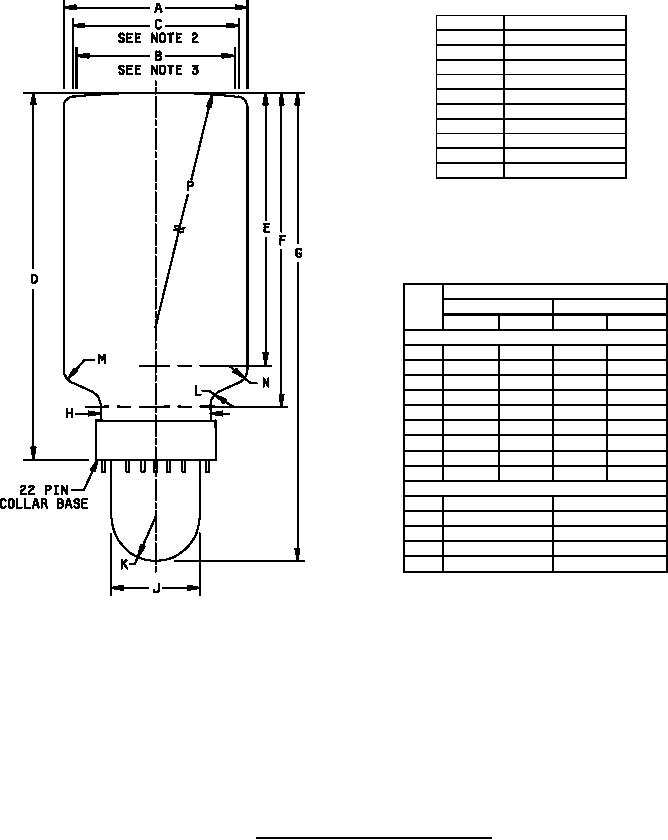
Dimensions
Ltr
Inches
Millimeters
Min
Max
Min
Max
Conformance inspection, part 2
A
7.312
7.688
185.72
195.28
B
6.750
---
171.45
---
C
7.031
---
178.59
---
D
14.500
15.000
368.30
381.00
E
10.500
11.000
266.70
279.40
F
12.250
12.750
311.15
323.85
G
18.688
19.000
474.68
482.60
H
4.312
4.500
109.52
114.30
J
3.469
3.656
88.11
92.86
Reference dimensions (see note 4)
K
.781 R
19.84 R
L
.500 R
12.70 R
M
5.063 R
128.60 R
N
.875 R
22.22 R
P
30.000 R
762.00 R
NOTES:
1. Index pin to align with ID2 trace ± 10°.
2. Minimum useful screen.
3. Minimum quality area.
4. Reference dimensions are for information only and are not required for
inspection purposes.
FIGURE 1. Outline drawing of electron tube type 7AGP19.
5