MIL-PRF-1/1100G
See footnotes at end of table.
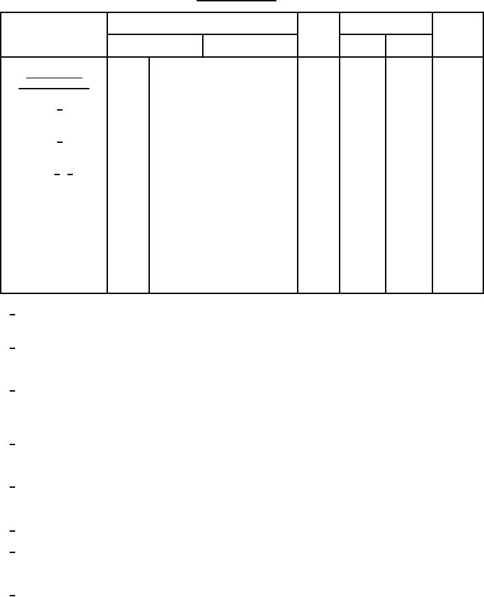
TABLE I. Group A Inspection - Continued.
Mil-Std-1311
Limits
Unit
Symbol
Inspection
Method
Conditions
Min
Max
Conformance
inspection, part 3
----
----
----
----
Group c; t = 96 hours "on" and 1
----
Life test (1) 1/
hour "off"; t = 500 hours
----
----
----
----
Life test (1); operation (2); Zg =
----
Life test (2) 6/
250 ohms; t = 500 hours
----
----
----
----
t = 500 hours
----
Life test (3) 1/ 3/
----
Life-test (1), (2), and
(3) end points:
V
500
----
egy
3246
Operation (1)
V dc
4,500
----
Ebb
egy = 500 V
3247
DC anode voltage
for conduction
µs
0.005
----
tj
egy = 500 V; Zg = 250 ohms
3261
Time jitter
TA = 75°C; t = 5 hours
----
----
----
3246
Operation at elevated
----
ambient temperature
1/ The circuit constants shall be chosen so that at epy = 25.0 kv under charging conditions: dik/dt = 2,500 a/µs
minimum; ib = 500 a minimum; tp = 2.0 ±0.2 µs; prr = 500 minimum. The grid pulse characteristics shall be: tp
= 2.0 µs maximum; tr = 0.25 µs minimum; internal impedance of driver = 250 ohms minimum.
2/ This test shall be conducted for a total of 5 consecutive hours with no more than three kickouts and with no
evidence of anode heating. The tube shall be started at Eres = 105 percent of the inscribed value and operate
at this value for 4 hours. At the start of the fifth hour and while the tube is still operating, the reservoir voltage
shall be lowered to 95 percent of the inscribed value and remain there for the final 1 hour of operation.
3/ The life test shall be intermittent, with the tube operating approximately half the total elapsed time, and held
without reservoir voltage or cathode-heater voltage approximately half the total time. The tube shall make a
minimum of four starts during each 24-hour period. The life-test duration is measured in operating hours.
Failure of the tube to operate following the minimum allowable cathode and reservoir heater warmup time
constitutes failure of the test.
4/ The tube shall operate satisfactorily on push-button starting within three attempts when the anode voltage (epy)
is applied to the tube under test in such a manner as to rise from 0 to 18 kv within 0.03 second. (The filter in the
rectifier shall be designed so that the epy reaches at least 9 kv within 0.015 second.) Any tube failing to start
within three attempts will be considered a failure.
5/ The anode circuit constants shall be so chosen that at resonant charging conditions; epy = 20 kv; ib = 200 a
minimum; dik/dt = 2,500 a/µs minimum. Output pulse; tp = 1.0 µs ±10 percent; prr = 1,200 minimum; epx = 5.0
kv. Grid pulse the same as note 1. Adjust reservoir voltage to optimum value for these test conditions. The
tube shall operate continuously for 20 minutes without continuous conduction.
6/ The optimum reservoir voltage for operation in accordance with operation (2) conditions shall be so determined
that the tube shall operate at 95 to 105 percent of the established reservoir voltage for these conditions.
7/ This test shall be performed simultaneously with the operation (1) test. An anode delay time measurement shall
be made at the end of 2 minutes, 4 minutes, and 30 minutes of the operation (1) test. The Ćtad measurement is
the numerical difference between the 2-minute and 4-minute, or 2-minute and 30-minute anode delay time
readings, whichever is greater.
8/ The tj shall be not greater than the amount specified after 120 seconds of anode operation.
3
For Parts Inquires call Parts Hangar, Inc (727) 493-0744
© Copyright 2015 Integrated Publishing, Inc.
A Service Disabled Veteran Owned Small Business