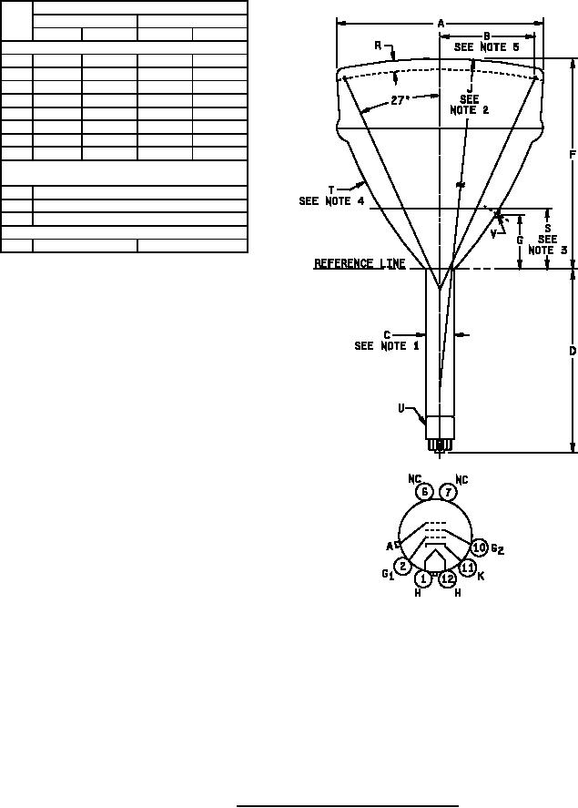
MIL-PRF-1/1056F
Dimensions
Ltr
Inches
Millimeters
Min
Max
Min
Max
Conformance inspection, part 2
A
12.340
12.500
313.44
317.50
B
5.500
---
139.70
---
C
1.384
1.500
35.16
38.10
D
8.060
8.440
204.72
214.38
F
10.310
10.690
261.87
271.53
G
2.630
3.380
66.80
85.85
R
.300
.400
7.62
10.16
S
2.970
3.090
75.44
78.49
Conformance inspection, part 3
(periodic check)
T
Bulb: J-99 1/2 A1, clear or filter glass
U
Base: B7-51 or B5-57
V
Contact: J1-21
Reference dimensions (see note 6)
J
40.000 R
1016.00 R
NOTES:
1. Dimension C applies to the entire length of neck below reference line. Reference line shall be determined by position
where gauge 1.500 inches (38.10 mm) ± .003 inch (0.08 mm) I. D. and 2.000 inches (50.80 mm) long will rest on bulb
cone.
2.
To meet the requirements of faceplate gauge as shown on figure 2.
Line established by ring gauge of I. D. 7.188 inches (182.58 mm) ± .016 inch (0.41 mm).
3.
4.
To meet the requirements of bulb contour gauge as shown on figure 3.
5.
Useful screen radius.
6.
Reference dimensions are for information only and are not required for inspection purposes.
FIGURE 1. Outline drawing of electron tube type 12SP7D.
5
For Parts Inquires call Parts Hangar, Inc (727) 493-0744
© Copyright 2015 Integrated Publishing, Inc.
A Service Disabled Veteran Owned Small Business