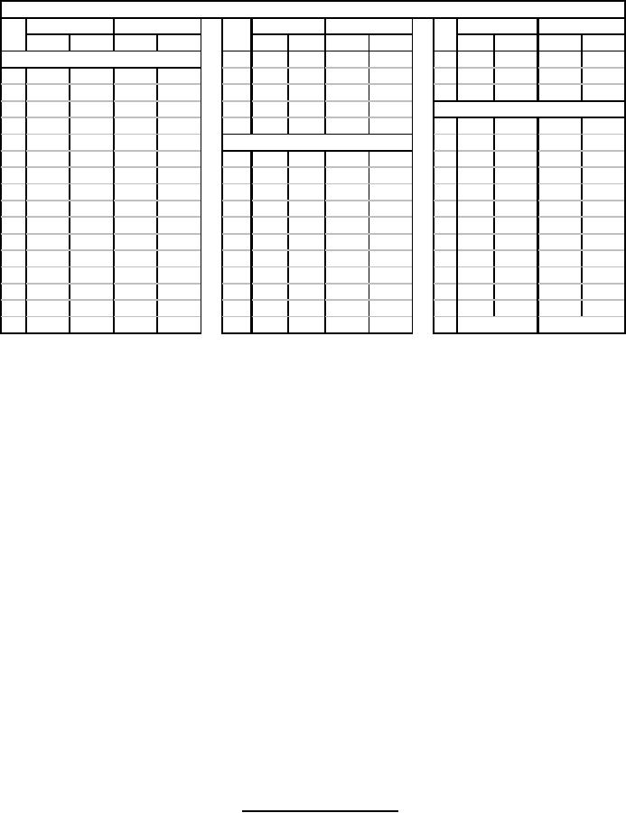
MIL-E-1/1315E
Dimensions
inch
mm
inch
mm
inch
mm
Ltr
Ltr
Ltr
min
max
min
max
min max
min
max
min
max
min
max
Quality Conformance Insp., Part 1
TT .285 .345
7.24
8.76
RR 4.375 4.875 111.13 123.83
A
.865
.880 21.97 22.35
UU .453 .503 11.51 12.76
SS
-
12.676
-
321.97
B
.905
.925 22.99 23.50
VV .435 .445 11.05 11.30
E
.385
-
9.78
-
WW .600 .655 15.24 16.64
Reference Only (No Inspection)
H
4.485 4.515 113.92 114.68
D 3.480 3.485 88.39 88.52
J
2.727 3.031 69.27 76.99
Quality Conformance Insp., Part 2
F .062
-
1.57
-
K
.454
.516 11.53 13.11
C
-
2.875
-
73.03
G .125
.130
3.18
3.30
L
5.700 5.950 144.78 151.13
P
-
7.125
-
180.98
M .370
.375
9.40
9.53
N
3.758 4.008 95.45 101.80
R
.750
-
19.05
-
Q
-
16.850
-
427.99
S
4.485 4.515 113.92 114.68
HH 5.500
-
139.70
-
T 3.120 3.124 79.25 79.35
V
4.064 4.314 103.23 109.50
JJ
-
.781
-
19.84
U
-
1.157
-
29.39
BB 8.132 8.382 206.55 212.90
KK 1.620
-
41.15
-
W 1.125 1.375 28.58 34.93
CC
.692
.722 17.58 18.34
LL 2.031 2.531 51.59 64.29
X .120
.125
3.05
3.18
DD
.205
.225
5.21
5.72
MM
-
6.176
-
155.87
Y .062
-
1.57
-
EE 2.485 2.515 63.12 63.88
NN 3.190 3.220 81.03 81.79
Z .068
.072
1.73
1.83
FF 6.125 6.625 155.58 168.28
PP 7.260 7.290 184.40 185.17
AA .120
.125
3.05
3.18
GG 16.375 16.625 415.93 422.28
QQ 4.000
-
101.60
-
XX
2.250
57.15
NOTES:
1. Reference plane "A" lies on finished surface of mounting brackets.
2. Reference plane "B" is perpendicular to reference plane "A" passing through the center of slots in brackets as
shown.
3. Reference plane "C" is perpendicular to reference planes "A" and "B" passing through the center of slots in
brackets as shown.
4. Includes angular as well as lateral deviation.
5. Parts on this centerline may vary from the location by .125 inch.
6. Refers to centerline of output as determined by the center of the flange.
7. Applies to 5.500 min. dia. for Marmon clamp.
8. Spline specifications: Periodic inspection (see note 14).
14 1/2° pressure angle
48 pitch
12 teeth
.256 pitch diameter
9. This .625 24 (must accept go thread pitch diameter gauge only) major diameter not to be less than .6145
(15.61 mm).
10. Bushing temperature.
11. Anode temperature
12. Tuner temperature
13. Common cathode connection.
14. Heater connection.
15. All solder joints or output and oil sealing flanges to provide a hermetic seal.
16. These surfaces to be coplanar within .025 in (0.635 mm).
17. A double diameter plug gauge 1.260 in (32.00 mm) O.D., .925 in (23.50 mm) I.D. with 0.0625 in (1.59 mm) X 45
seconds chamfer on the O.D. shall pass over the cathode terminal and drop a minimum .125 in (3.18 mm) below
the surface indicated.
18. A hole on the upper corona shield of the cathode bushing to be used for heater adapter orientation shall lie within
2 degrees of a plane passing through the center of the cathode bushing and the centerline of the output.
19. Oil vent pipe termination mates with Wiggins P/N P1705. A Wiggins P/N P1705 connector, or equal, with
threaded oil-tight cap, shall be installed on each tube when delivered by the manufacturer.
FIGURE 1. Outline drawing of type 6310 - Continued
6
For Parts Inquires call Parts Hangar, Inc (727) 493-0744
© Copyright 2015 Integrated Publishing, Inc.
A Service Disabled Veteran Owned Small Business