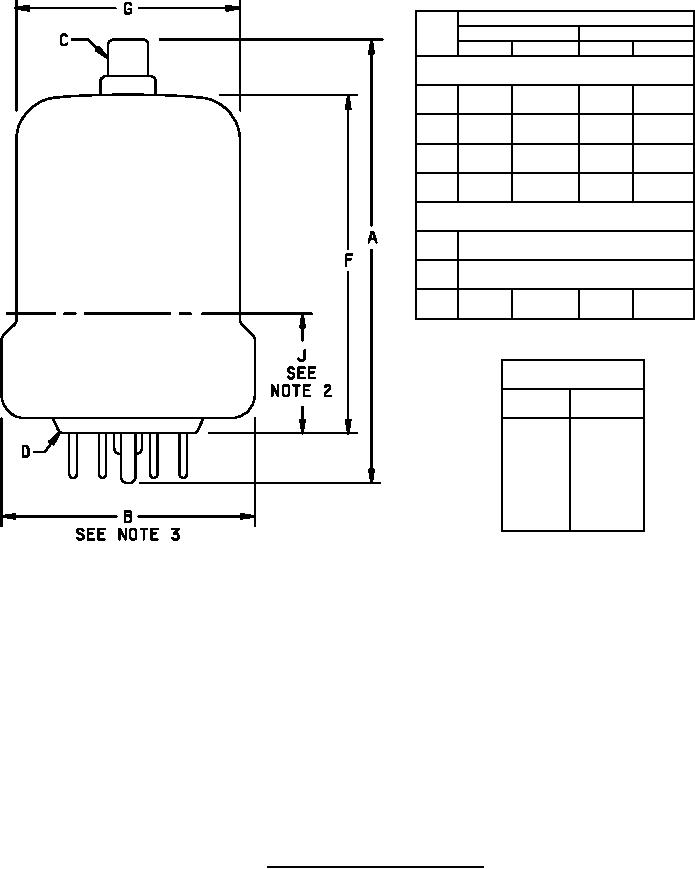
MIL-PRF-1/876G
Dimensions
Ltr
Inches
Millimeters
Min
Max
Min
Max
Conformance inspection, part 2
A
4.000
4.375
101.60
111.13
B
---
2.375
---
60.33
G
---
2.060
---
52.32
J
.844
1.219
21.44
30.96
Conformance inspection, part 3 (see note 4)
C
Cap: C1-22 (EIA) (See note 5)
D
Base: E5-59 (See note 2) (EIA)
F
2.938
3.313
74.63
84.15
Pin connections
Pin No.
Element
1
f
2
g2
4
g1
6
g2
7
f
Cap
a
NOTES:
1. For pin alignment, use JEDEC gauge GE7-6. A molded glass flare base with pin configuration identical with that of base E5-59
may be used.
2. With base pins inserted into gauge GE7-6, a flat plate gauge with a 2.063 ± .003 inches (52.40 ± 0.08 mm) diameter hole is
passed over diameter G until it stops at position defined by dimension J. Dimension J shall then be gauged between bottom
surface of flat-plate gauge and top surface of gauge GE7-6 with surfaces of both gauges parallel. The 2.063 inches (52.40 mm)
diameter hole of the flat-plate gauge and .500 inch (12.70 mm) diameter hole of gauge GE7-6 shall be concentric within .150 inch
(3.81 mm).
3. A ring gauge .125 ± .010 inch (3.18 ± 0.26 mm) thick and 2.125 inches (53.98 mm) minimum and 2.128 inches (54.05 mm)
maximum inside diameter shall not pass over diameter B when tried at an angle.
4. Dimensions shall be checked yearly. An accept on zero defect sampling plan shall be used on a sample of three tubes. In the
event of failure, the test will be made as a part of conformance inspection, part 2, in accordance with the accept on zero (c=0)
sampling plan of MIL-PRF-1, Table III, for category XV. The regular yearly sampling plan may be reinstated after three
consecutive samples have been accepted.
5. In the referenced EIA standard Cap C1-22, the dimension .656" MIN should be .328" MIN.
FIGURE 1. Outline drawing of electron tube type 8165.
4