MIL-PRF-1/746H
Dimensions
Ltr
Inches
Millimeters
Min
Max
Min
Max
Conformance inspection, part 1
A
2.969
3.219
75.41
81.76
B
.990
1.000
25.15
25.40
C
.880
.890
22.35
22.61
F
1.375
1.500
34.93
38.10
M
.303
.323
7.70
8.20
Conformance inspection, part 2
G
.560
.610
14.22
15.49
H
.250
.312
6.35
7.92
J
.257
.287
6.53
7.29
Conformance inspection, part 3
D
---
.750
---
19.05
25°
35°
25°
35°
K
N
.610
.656
15.49
16.66
P
.807
.822
20.50
20.88
Pin connections
1
g1
Q
.245
.255
6.22
6.48
2
h
3
k
R
Base: A4-76
4
h
Lower disk
g2
S
Cap: C1-3
Upper disk
g3
Nominal dimensions
Cap
r
L
.250
6.35
NOTES:
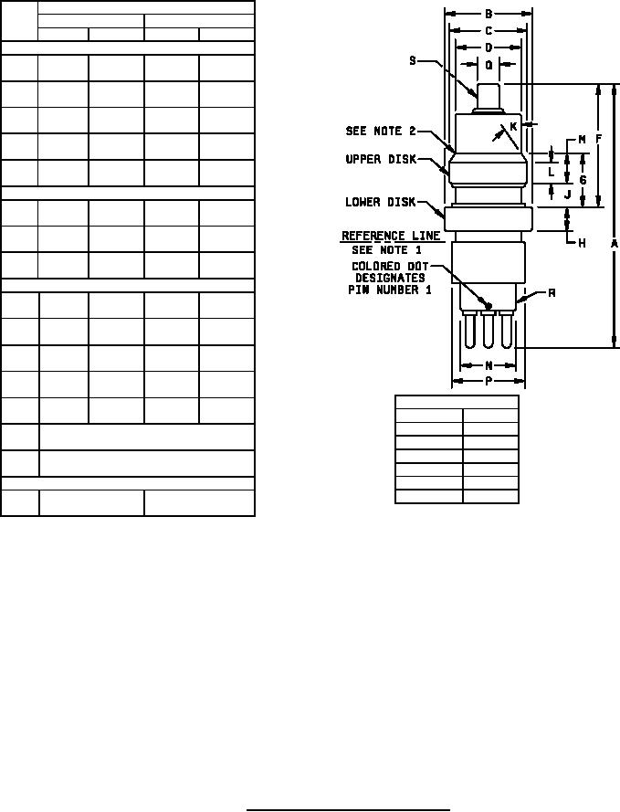
1. For dimensions below reference line refer to base A4-76.
`
2.
Space between glass and upper disk edge or backing ring shall be .030 inch (0.76 mm) maximum. Conformance inspection,
part 2, shall apply.
3.
Diameters B and C shall be concentric within .025 inch (0.63 mm) TIR and shall form circular cylinder within a range of .006
inch (0.15 mm). Allowable radius at ends of cylinder shall be .030 inch (0.76 mm) maximum. Conformance inspection, part
2, shall apply.
4.
Tube shall be tested in concentricity gauge specified on drawing 199-JAN. Gauge readings on diameters shall be as follows:
Diameter
Eccentricity
D
.050 max
N
.060 max
P
.060 max
Q
.040 max
5.
All concentricity measurements shall be conformance inspection, part 2.
6.
Pin No. 1 shall be identified by an index mark (colored dot or other.)
FIGURE 1. Outline drawing of electron tube type 6BMA.
4