MIL-PRF-1/746H
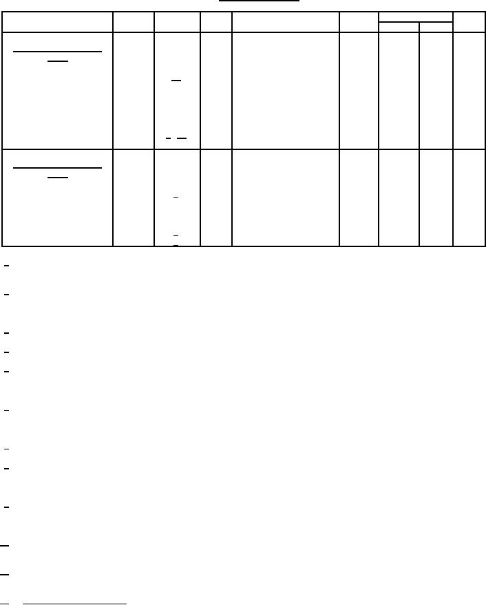
TABLE I. Testing and inspection.
Limits
Inspection
Method
Notes
Test
Conditions
Symbol
Min
Max
Unit
Conformance inspection,
part 2
Secureness of base, cap,
1101
10/
---
---
---
---
---
or insert
Low-frequency vibration
1031
---
---
No voltages
---
---
---
---
µs
Time jitter
4318
3/ 11/
---
Prr = 4,000 (approximate)
tj
---
0.2
Conformance inspection,
part 3
Life test
---
2/
1
Group C
t
500
---
hrs
---
Life-test end points:
4250
8/
Power output (3)
2
Po
8
---
mW
9/
4250
Power output (4)
2
Po
16
---
mW
1/
Unless otherwise specified, the acceptance level for all tests listed under conformance inspection, part 1, shall be 1.0, inspection
level II.
2/
Test tube with 1,000 MHz test cavity as specified on Drawing 166-JAN. Frequency approximately 1,000 MHz. Operate tube in N
= 1 mode (1.75 cycles for complete transit). Adjust Er for maximum power output. Adjust output coupling loop for maximum
power output.
3/
Test in signal generator TS-419/U, or equivalent.
4/
Static test; tube not oscillating.
5/
Test tube with 800 MHz test cavity as specified on Drawing 166-JAN. Adjust cavity to resonate at 800.5 MHz with standard plug
as specified on Drawing 197-JAN. Operate tube in N = 1 mode (1.75 cycles for complete transit). Adjust Er for maximum power
output. Adjust output coupling loop for maximum power output.
6/
Test tube with 2,200 MHz test cavity as specified on Drawing 166-JAN. Adjust cavity to resonate at 2,113.8 MHz with standard
plug as specified on Drawing 197-JAN. Operate tube in N = 1 mode (1.75 cycles for complete transit). Adjust Er for maximum
power output. Adjust output coupling loop for maximum power output.
7/
Reduce Ef to 5.7 V while tube is oscillating. The cathode emission shall not exceed the limit shown.
8/
Test tube with 1,150 MHz test cavity as specified on Drawing 166-JAN. Adjust cavity to resonate at 1,130.6 MHz with standard
plug as specified on Drawing 197-JAN. Operate tube in N = 2 mode (2.75 cycles for complete transit). Adjust Er for maximum
power output. Adjust output coupling loop for maximum power output.
9/
Test tube with 2,750 MHz test cavity as specified on Drawing 166-JAN. Adjust cavity to resonate at 2,569.2 MHz with standard
plug as specified on Drawing 197-JAN. Operate tube in N = 2 mode (2.75 cycles for complete transit). Adjust Er for maximum
power output. Adjust output coupling loop for maximum power output.
10/
W ater-immersion test omitted. Torque shall be applied between upper disk (g3) and molded portion of base and shall be 20 inch-
pounds.
11/
Adjust Er tracking from minimum jitter over the range from 900 to 2,100 MHz. When recheck measurements are made at
locations other than the point of manufacture, an addition of 0.05 µs shall be allowed on the specified limits.
12/
Changes from previous issue. Revision letters are not used in this revision to identify changes with respect to the previous issue,
due to the extensiveness of the changes.
3