MIL-PRF-1/664F
Dimensions
Ltr
Inches
Millimeter
Min
Max
Min
Max
Conformance inspection, part 2
A
9.500
10.500
241.30
266.70
B
2.375
2.750
60.32
69.85
C
4.875
5.125
123.82
130.18
M
1.437
1.687
36.50
42.85
Conformance inspection, part 3
(see note 4)
D
2.562
2.812
65.07
71.42
E
2.562
2.687
65.07
68.25
F
1.687
1.812
42.85
46.02
G
.437
.562
11.10
14.27
H
.312
.437
7.92
11.10
J
5.375
5.875
136.52
149.22
K
7.250
7.750
184.15
196.85
L
6.375
6.625
161.92
168.28
N
1.562
1.812
39.67
46.02
P
.812
.937
20.62
23.80
Q
2.187
2.437
55.55
61.90
NOTES:
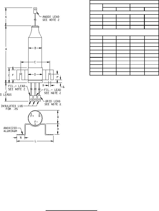
1. Use of ceramic beads or fiber glass sleeves with silicone resin impregnation as lead insulators is optional.
2. Leads:
Flexible; silicone-impregnated glass fiber insulation, class C-2 or better; as follows: (see notes 3 and 5)
Anode:
at top; lug for .25 inch nominal (6.4 mm) stud, lug width .41 inch nominal (10.4 mm).
Fil. +:
at base; insulated lug for .25 inch nominal (6.4 mm) stud, lug width .47 inch nominal (11.9 mm).
Fil. - :
at base; insulated lug for .25 inch nominal (6.4 mm) stud, lug width .41 inch nominal (10.4 mm).
Grid:
at base; insulated lug for .25 inch nominal (6.4 mm) stud, lug width .47 inch nominal (11.9 mm).
3. Each lead shall be clearly marked as specified herein.
FIGURE 1. Outline drawing of electron tube type 5665.
3
For Parts Inquires call Parts Hangar, Inc (727) 493-0744
© Copyright 2015 Integrated Publishing, Inc.
A Service Disabled Veteran Owned Small Business