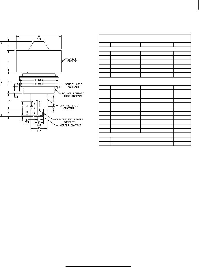
MIL-PRF-1/302P
Dimensions in inches with metric
equivalents (mm) in parentheses
Ltr
Minimum
Maximum
Notes
Conformance inspection, part 2
A
2.750 (69.85)
B
1.615 (41.02)
1.635 (41.53)
D
1.417 (35.99)
1.433 (36.40)
E
0.587 (14.91)
0.597 (15.16)
F
0.317 (8.05)
0.327 (8.31)
G
0.088 (2.24)
0.098 (2.49)
Conformance inspection, part 3
(See note 4)
C
1.406 (35.71)
H
0.313 (7.95)
J
0.719 (18.26)
0.781 (19.84)
2
K
0.750 (19.05)
0.813 (20.65)
L
0.188 (4.78)
2
M
0.500 (12.70)
0.578 (14.68)
N
0.234 (5.94)
0.266 (6.76)
P
0.031 (0.79)
0.063 (1.60)
T
0.344 (8.74)
2
U
0.406 (10.31)
2
V
0.469 (11.91)
2
Reference dimensions
1
R
0.094 (2.39)
S
0.125 (3.18)
NOTES:
1. Reference dimensions are for information only and are not required for inspection purposes.
2. Available contact length.
3. Dome contour shall be such that it will be contained within crosshatch area of template shown on figure 3.
Optical comparator techniques are normally used for this purpose.
4. See note 7 of table I.
FIGURE I. Outline drawing of electron tube type 8172.
5
For Parts Inquires call Parts Hangar, Inc (727) 493-0744
© Copyright 2015 Integrated Publishing, Inc.
A Service Disabled Veteran Owned Small Business