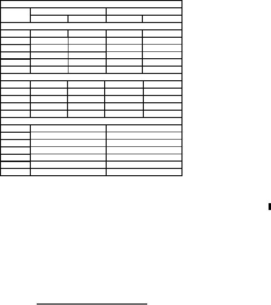
MIL-PRF-1/299G
Dimensions
Ltr
Inches
Millimeters
Min
Max
Min
Max
Conformance inspection, part 1 (see note 1)
A
4.828
4.888
122.63
124.16
K
3.008
76.40
P
.187
4.76
Q
.165
.195
4.19
4.95
R
.347
.377
8.81
9.58
T
.812
20.64
Conformance inspection, part 2
C
2.490
2.510
63.25
63.75
E
2.240
2.260
56.90
57.40
L
3.203
3.233
81.36
81.85
M
1.703
1.733
43.26
44.02
N
1.508
38.30
Reference dimensions
B
4.125
104.78
D
.812
20.64
F
.187
4.76
G
2.625
66.68
H
.250
6.35
J
.125
3.18
S
.218
5.56
NOTES:
1.
This specification sheet uses accept on zero defect sampling plan in accordance with MIL-PRF-1, table III.
2.
Exhaust tube shall not extend beyond flange more than 0.25 (6.35 mm) inch.
3.
Gasket in accordance with Drawing 189 JAN. Gasket to be securely attached.
4.
Dimension Q shall be measured prior to the attachment of the gasket to the tube.
5.
Edges may be rounded.
6.
Nickel plating or Rhodium flash over silver plating optional. If nickel plating is required, it is recommended that it be used only
when other platings cannot meet performance requirements. Surface plating shall meet and enable the Gas Switching tube
to meet all interface and performance requirements.
FIGURE 1. Outline drawing of electron tube type 5927 - Continued.
5
For Parts Inquires call Parts Hangar, Inc (727) 493-0744
© Copyright 2015 Integrated Publishing, Inc.
A Service Disabled Veteran Owned Small Business