MIL-PRF-1/28H
Table 1. Testing and Inspection -Continued.
Inspection
Method
Conditions
Symbol
Limits
Limits
Units
Min
Max
Quality conformance
inspection, part 3
Life-test provisions
---
Group C; t = 500 hours (see note 4)
---
---
---
---
Life-test end points
---
Anode current (see notes 10 and 18)
---
---
---
---
NOTES:
1/ Overall anode to cathode dc supply voltage.
2/ Anode to 9th dynode dc voltage.
3/ An anode load resistance of at least 10,000 ohms is recommended for a protective resistance.
4/ Ebb = 1,000 V adjust luminous flux at cathode initially to obtain Ib = 0.1 mA dc. Color temperature
shall be greater than 2,000 K.
5/ Capacitance between anode and dy9, all other elements grounded.
6/ Capacitance between anode and all other elements.
7/ Test circuit and test equipment requirements:
A bleeder network to provide equal voltage per stage; 8-megohm series resistance for cathode, and all
dynodes excluding the last dynode (9th); 1-megohm series resistance for last dynode (9th) and anode; a
regulated (0.1 percent) power supply with low ripple (0.05 volts peck-to-peck maximum) as a voltage
source; a sensitive dc microammeter to determine anode current; an oscilloscope, with a low-capacity
divider, is connected across the anode load resistance (1 megohm) to monitor noise and breakdown;
base pins of photomultiplier under test connected so that the degradation of breakdown characteristics
is minimized; a vacuum pump, low-pressure chamber and manometer; a light source with an adjustable
iris and sandblasted glass. Mask tube with lightproof material. The light source should be located so that
light from it is striking the cathode of the photomultiplier. (Light from the light source should be the only
light striking the cathode.) The opening of the iris is varied to obtain approximately 10 microamperes of
anode current. Observe the tube noise signal as displayed by the oscilloscope. Reduce pressure of vacuum
chamber to 130 mmHg. The tube should be subjected to this pressure for a period of 2 minutes. During
pressure reduction, the tube noise signal, as displayed by the oscilloscope, should be observed to
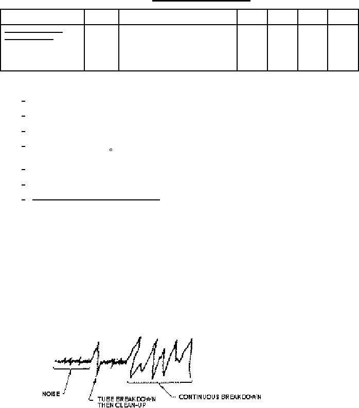
determine tube breakdown. When breakdown occurs, the signal being monitored by the oscilloscope will
resemble the following:
When continuous breakdown occurs, a change in anode current will result.
3