MIL-PRF-1/1726B
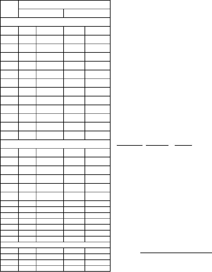
Dimensions
NOTES:
LTR
1. Insulation material is required between heater and
Inches
Millimeters
heater-cathode and shall be securely affixed.
2. Dimensions shall be checked during the the initial production
Conformance inspection, part 2
and once each succeeding 12-calendar months in which there
is production. A regular double sampling plan shall be used,
Min
Max
Min
Max
with the first sample of three tubes with an acceptance number
of zero, and a second sample of three tubes with a combined
A
1.815
1.875
46.10
47.63
acceptance number of one. In the event of failure, the test shall
be made as a part of conformance inspection, part, 2, code
B
---
1.534
---
38.96
level D, with an acceptance level of 6.5. The regular "12-
calendar month" double sampling plan shall be reinstated after
C
---
1.475
---
37.47
three consecutive samples have been accepted.
3. Silver plated 30 MSI minimum.
D
1.289
1.329
32.74
33.76
4. Plating not required over radiator and radiator support
of copper, aluminum, or approved equivalent.
F
.970
1.010
24.64
25.65
5. This surface shall be used for measurement of anode
shank temperature.
G
.462
.477
11.73
12.12
6. Holes for tube extractor through top fin only.
J
.766
.826
19.46
20.98
7. Inner edge of heater and outer edge of cathode rf
connection shall be free from burrs and sharp edges.
N
1.025
1.035
26.04
26.29
8. This fin shall withstand a 6-inch drop test without
loosening and without distortion as judged by ability
R
.655
.665
16.64
16.89
to maintain dimension K. Note 2 shall apply.
9. Distortion of fins permissible provided distance between
T
.213
.223
5.41
5.66
adjacent fins at any point on circumference meets
tolerances for dimension K.
U
.315
.325
8.00
8.26
10. Eccentricity of contact surfaces shall be gauged from
center line of reference and shall be as follows.
Z
1.120
1.130
28.45
28.70
Note 2 shall apply.
Conformance inspection, part 3 (see note 2)
Reference
Contact surface TIR maximum
E
.125
.185
3.18
4.70
Anode
.020
Cathode
Grid
.020
Cathode
H
---
.040
---
1.02
Heater
.012
Cathode
K
.025
.046
0.64
1.17
11. Diameters N, R, T, and U shall apply throughout
entire contact areas as defined by dimensions
L
1.234
1.264
31.34
32.11
AA, AB, AC, and AD, respectively.
12. Dimensions in electrode contact areas table are for
M
1.180
1.195
29.97
30.35
socket design purposes and are not intended for
inspection purposes.
P
.772
.792
19.61
20.12
13. This surface shall not be used for clamping or locating.
Q
.650
.850
16.51
21.59
S
---
.545
---
13.84
V
---
.086
---
2.18
W
---
.100 RAD
---
2.54 RAD
AE
.420
---
10.67
---
AF
.105
.145
2.67
3.68
AG
---
.035 RAD
---
0.89 RAD
Electrode contact areas - see note 12)
AA
.035
.361
0.89
9.17
FIGURE 1. Outline drawing of electron tube type 8533W -
Continued.
AB
1.185
1.265
30.10
32.13
AC
1.534
1.728
38.96
43.89
AD
1.475
1.815
37.47
46.10
7
For Parts Inquires call Parts Hangar, Inc (727) 493-0744
© Copyright 2015 Integrated Publishing, Inc.
A Service Disabled Veteran Owned Small Business