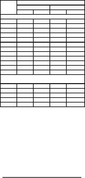
MIL-PRF-1/1716B
Dimensions
Ltr
Inches
Millimeters
Min
Max
Min
Max
Conformance inspection, part 2
C
.600
.760
15.24
19.30
D
1.896
1.936
48.16
49.17
E
3.133
3.173
79.58
80.59
F
3.792
3.832
96.32
97.33
G
3.980
4.020
101.09
102.11
H
.188
---
4.78
---
J
.188
---
4.78
---
K
.188
---
4.78
---
L
1.764
1.826
44.81
46.38
P
8.625
9.125
219.08
231.78
R
.986
1.050
25.04
26.67
T
.375
---
9.53
---
Conformance inspection, part 3
(periodic check)
A
6.928
7.050
175.97
179.07
B
.855
.895
21.72
22.73
M
4.186
4.568
106.32
116.03
N
2.412
2.788
61.26
70.82
S
3.412
3.788
86.66
96.22
NOTES:
1. The total indicator reading (the sum of the positive and negative deflection shown by the indicator when
measuring the eccentricity of the surface with respect to another, with the reference axis established) of
the screen grid and filament contact surfaces shall not exceed .040 inch (1.02 mm) with respect to the
control grid and anode contact surfaces when the latter surfaces are rotated on rollers at the points
indicated by the arrows. (Conformance inspection, part 2 shall apply.)
2. Letters H, J, K, N, and T also represent contact surfaces.
3. Top cap outline optional provided it meets requirements of dimensions B and T.
FIGURE 1. Outline drawing of electron tube type 8171 - Continued.
Custodian:
Preparing activity:
Army - CR
DLA - CC
Air Force - 99
DLA - CC
(Project 5960-3694)
Review activities:
Army - AR
Air Force - 11, 19
6