MIL-PRF-1/1702C
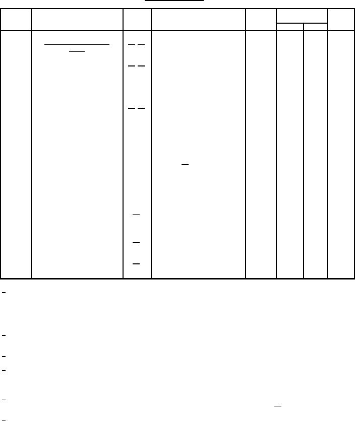
TABLE I. Testing and inspection - Continued.
Method
Requirement or test
Notes
Conditions
Symbol
Limits
Unit
Min
Max
14/ 15/
Conformance inspection,
part 3
mV ac
250
---
Ep
10/ 16/
1031
F = 55 Hz to 500 Hz;
Variable-frequency vibration
Acceleration = 10 G (peak);
Ebb = 300 V dc;
Rp = 10,000 ohms;
Ec/Ib = 10 mA dc
---
---
---
---
No voltages
---
Torque
10/ 17/
---
Torque-test end point
-10
---
Ic
1266
Total grid current
µA dc
---
---
---
Condition A; use fixture in
1042
Shock, specified pulse
---
accordance with Drawing
280-JAN (21/); no voltages
---
Shock, specified pulse-test
end point
-10
---
Ic
1266
Total grid current
µA dc
---
---
---
1002
Barometric pressure, reduced
Pressure = 35 mmHg (max);
18/
---
Voltage = 1,800 V ac, 60 Hz;
TA = 30°C ±10°C
---
---
---
Life
---
19/
Group S, monthly; Ef = 5.7 V;
---
Filament standby
25
---
Life-test end point
---
19/
ĆIb
%
(1,000 hours)
1/
The transit-time heating effect of the cathode may require compensation by a reduction in heater voltage after dynamic operation of
the tube has started. The back heating is a function of frequency, grid current, grid bias, anode current, duty cycle, and circuit
design and adjustment. There is an optimum heater voltage which will maintain the cathode at the correct operating temperature
for a particular set of operating conditions. A maximum variation of ± 5 percent from optimum is permitted. No reduction in heater
voltage is required up to and including 500 MHz.
2/
The regulation or series-anode-supply impedance, or both, shall limit the instantaneous peak current, with the tube considered as a
short circuit, to a maximum of 10 times the specified maximum current rating.
3/
The maximum instantaneous peak grid-cathode voltage shall be within the range of +250 to -750 volts.
4/
Sufficient conduction, convection, and forced-air cooling shall be provided to limit the envelope and anode shank temperature to the
specified value under all operating conditions. Reliability will be seriously impaired if this maximum is exceeded. W here emphasis
is placed on long and reliable life, lower temperatures should be used.
5/
At an anode dissipation of 100 watts and with an incoming air temperature of 25°C maximum at sea level, a minimum air flow of
12.5 cfm must be directed across the anode cooler, using the cowl as shown on Drawing 157-JAN (21/), or equivalent.
6/
Sufficient conduction, convection, and forced-air cooling may be used in all electrical tests involving application of heater voltage to
maintain the anode shank and seal temperatures within the specified maximum value.
3
For Parts Inquires call Parts Hangar, Inc (727) 493-0744
© Copyright 2015 Integrated Publishing, Inc.
A Service Disabled Veteran Owned Small Business